I-lock coupler

Pending Publication Date: 2022-02-03
CASCADE CORP
View PDF0 Cites 0 Cited by
  • Summary
  • Abstract
  • Description
  • Claims
  • Application Information

AI Technical Summary

Benefits of technology

The I-Lock coupler is a special kind of connector that allows for quick and safe coupling between hydraulic circuits. It features a safety mechanism that automatically locks when the connector is decoupled, ensuring safe use. Additionally, the coupler is designed to use the hydraulic supply from the original equipment manufacturer (OEM), which simplifies the installation process. This design also minimizes the time the safety locking mechanism is open, reducing the risk of accidents.

Problems solved by technology

These quick couplers lack the safety features and ease of use of the present design.

Method used


Image

  • I-lock coupler
  • I-lock coupler
  • I-lock coupler

Examples


first embodiment

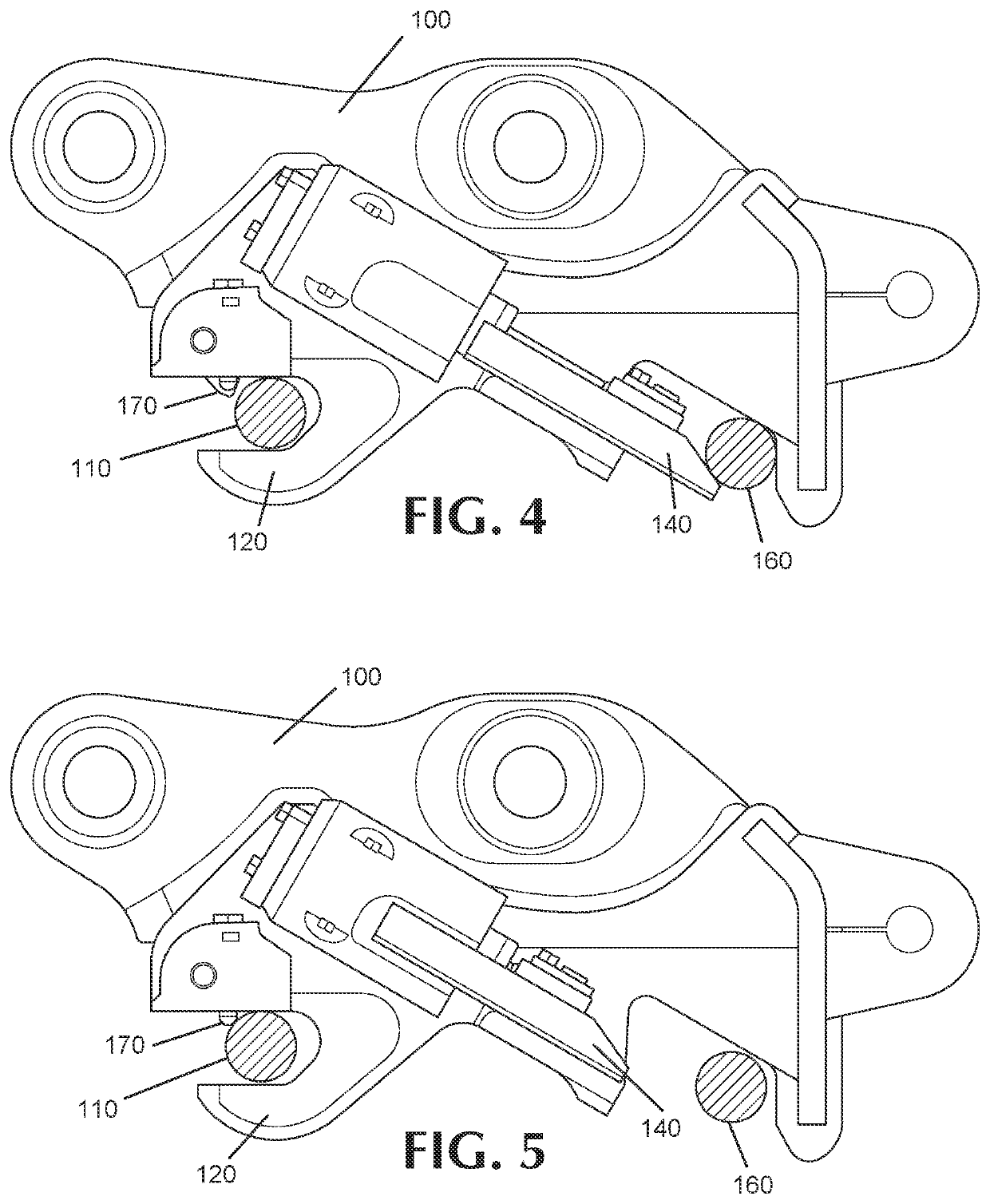
[0024]FIGS. 4, 5 and 8 show this disclosure. To engage and disengage an attachment, front pin 110 passes safety knuckle 130 and plunger 170. Plunger 170 is pushed upward by front pin 110 and then automatically releases down behind front pin 110FIG. 8 shows valve 180 which drives plunger 170 and stores hydraulic pressure to release it.

second embodiment

[0025]FIGS. 6 and 9 show this disclosure. To engage and disengage an attachment, front pin 110 passes safety knuckle 130 and actuator 190. For engagement, actuator 190 rotates to press lever 200 upwards engaging valve 210.

third embodiment

[0026]FIGS. 7 and 10 show this disclosure. To engage and disengage an attachment, front pin 110 passes safety knuckle 130 and alternate actuator 220. Alternate actuator 220 has at least two corners 230. Upon rotation of actuator 220, corner 230 causes the actuator to engage with valve 240.

[0027]FIGS. 11-16 are flowcharts illustrating operation of the embodiments.

[0028]FIG. 11 illustrates a Typical OEM Supplied Valve. This typically is supplied as an OEM option that is installed at the factory. It consists as a 2-line configuration which supplies oil to the “extend” and “retract” hoses.

[0029]Item 110 of FIG. 11 is a Typical OEM Supplied Valve. Item 111 of FIG. 11 is a 4-way, 2-position Solenoid operated Directional Valve. In the normal state, oil is continually supplied to the “extend” function of the coupler which maintains positive pressure on the extend side of the wedge cylinder. The “retract” line is vented to the low pressure reservoir (tank). When powered it shifts the pressur...


PUM


Abstract

A quick coupler which features a safety mechanism which facilitates ease of use and assures safe use in the workplace by use of hydraulic circuits designed to automatically reset the safety locking mechanism on intentional removal of a front pin, including use of a 2-line hydraulic supply to the coupler.

Description

CROSS-REFERENCE TO RELATED APPLICATIONS[0001]This application claims the benefit of U.S. Provisional Patent Application No. 63 / 058,232 filed Jul. 29, 2020.BACKGROUND OF THE INVENTION[0002]Safety is the most important issue in the workplace. Observing safety guidelines, equipment capacities and using common sense will provide a work environment that is safe and efficient for workers and customers. A variety of quick couplers for use with lift trucks and heavy equipment are known in the art. These quick couplers lack the safety features and ease of use of the present design.SUMMARY OF THE INVENTION[0003]The I-Lock coupler is a quick coupler which features an innovative safety mechanism which facilitates ease of use and assures safe use in the workplace.[0004]The hydraulic circuits of the coupler are designed to automatically reset the safety locking mechanism on intentional removal of a front pin. This design has the advantage of being able to utilize an OEM supplied 2-line hydraulic ...

Claims


Application Information

Patent Timeline
IPC IPC(8): E02F3/36
CPCE02F3/3663E02F3/3622E02F3/3627E02F3/364E02F3/365E02F9/226E02F9/2296
Inventor WALTHERS, CHRISTOPHER M.SNAZA, WESLEY A.
Owner CASCADE CORP
Why Eureka
Try Eureka