Ferrite crossed-loop antenna of optimal geometry and construction and method of forming same

Inactive Publication Date: 2000-01-11
MEGAPULSE
View PDF7 Cites 24 Cited by
  • Summary
  • Abstract
  • Description
  • Claims
  • Application Information

AI Technical Summary

Benefits of technology

From a broader viewpoint, the invention contemplates a method of minimizing the volume and weight of a crossed winding loop antenna, that comprises, inserting within t

Problems solved by technology

When using whip and similar antennas in applications such as vehicle tracking, signal losses caused by buildings in cities and other similar obstructions as well as E-field interference effects, as from the power lines and P-static ef

Method used


Image

  • Ferrite crossed-loop antenna of optimal geometry and construction and method of forming same
  • Ferrite crossed-loop antenna of optimal geometry and construction and method of forming same
  • Ferrite crossed-loop antenna of optimal geometry and construction and method of forming same

Examples


Embodiment Construction

It is now in order to describe the preferred construction, operation and resulting improved performance of the ferrite magnetic crossed loop antennas of the invention for such uses as to detect Loran-C radio navigation signals and the like, employing the "optimum" geometry of the very high permeability-hollow ferrite core crossed-loop antenna, underlying the present invention.

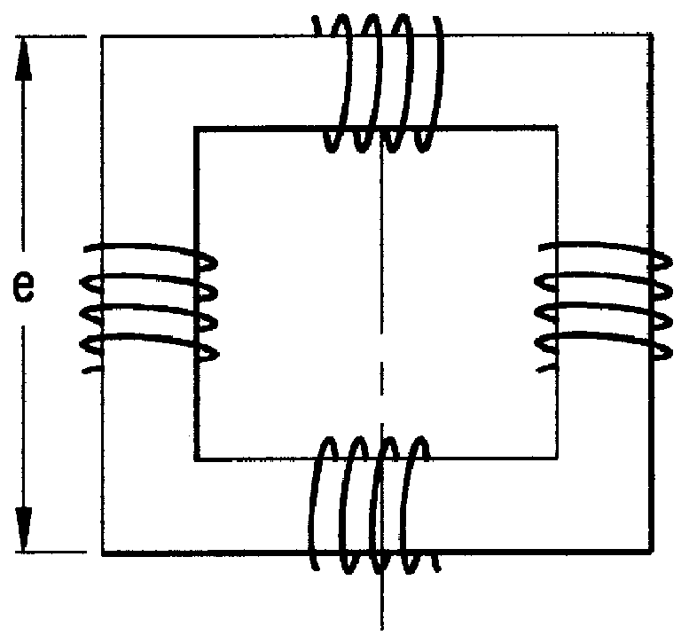
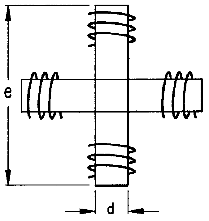
Conventional prior art crossed-loop antennas, as before described, are shown in FIGS. 1(a) and 1(b). Two solid ferrite rods forming a cross are shown in FIG. 1(a), and ferrite rods forming a square frame are shown in FIG. 1(b). The (b) geometry has almost twice the amount of ferrite as compared to (a), but it captures more flux lines, thus increasing the induced signals.

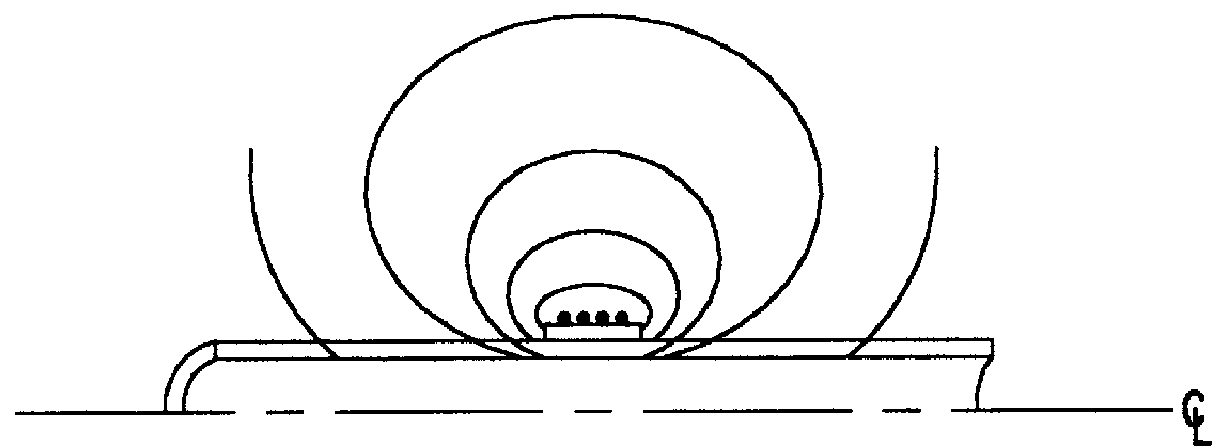
It has been shown, as presented in FIGS. 2(a)-(d), that the use of magnetic material increases flux lines in a single rod loop. The magnetic core material concentrates the flux lines through the winding thereby increasing the induced voltage and...


PUM


Abstract

A novel loop antenna containing a thin-walled ferrite box or other hollow; magnetic core structure of high permeability (considerably greater than 100), particularly useful for crossed loop antennas, and of optimal geometry and configuration for minimum volume, weight and space.

Description

The present invention relates to loop antennas, particularly of the magnetic core type, and more specifically to pairs of orthogonally crossed ferrite loop antennas useful in position location determination from the reception thereby of radio signal transmissions such as navigation signals, including Loran C type navigation transmissions, GPS and other vehicle location applications and the like and methods of forming the same.Loop antennas, including arrays involving orthogonally and otherwise relatively positioned or crossed loops have been used for many years in myriads of radio location and homing systems.For purposes such as the above mentioned reception of radio navigation signals and the like, specifically Loran-C type transmissions, however, resort has been had to the use of linear antennas, such as whip antennas and the like, wherein, unlike loop antennas, all the received signals travel a single path into the receiver front end, with time difference measurements of signal a...

Claims


Application Information

Patent Timeline
IPC IPC(8): H01Q7/06H01Q7/08H01Q7/00
CPCH01Q7/06H01Q7/08
Inventor JOHANNESSEN, PAUL R.
Owner MEGAPULSE
Why Eureka
Try Eureka