Rotary resistance device

a rotary resistance and device technology, applied in the direction of magnets, mechanical equipment, magnetic bodies, etc., can solve the problem of disadvantageous expansion of the volume of the internal rotary resistance devi

Active Publication Date: 2015-08-27
NAT TAIPEI UNIV OF TECH
View PDF0 Cites 0 Cited by
  • Summary
  • Abstract
  • Description
  • Claims
  • Application Information

AI Technical Summary

Benefits of technology

[0016]With the magnetic field generating assembly, the magnetizable outer cylinder and the magnetorheological fluid arranged in the above manner to form the rotary resistance device of the present invention, the magnetizable outer cylinder can rotate about and relative to the magnetic field generating assembly, and the magnetic fields produced by the magnetic field generating assembly can act on the magnetorheological fluid, which causes the solid magnetic particles in the magnetorheological fluid to align themselves with the direction of the magnetic lines of force between the N pole and the S pole and accordingly form a plurality of particle chains between the two poles. The formation of the particle chains in the magnetorheological fluid produces an effect of anti-shear stress and accordingly provides a resistance to the magnetizable outer cylinder

Problems solved by technology

In this case, the internal rotary resistance device would have a disadvantageously expanded volume.

Method used


Image

  • Rotary resistance device
  • Rotary resistance device
  • Rotary resistance device

Examples


Embodiment Construction

[0022]The present invention will now be described with some preferred embodiments thereof and with reference to the accompanying drawings. For the purpose of easy to understand, elements that are the same in the preferred embodiments are denoted by the same reference numerals.

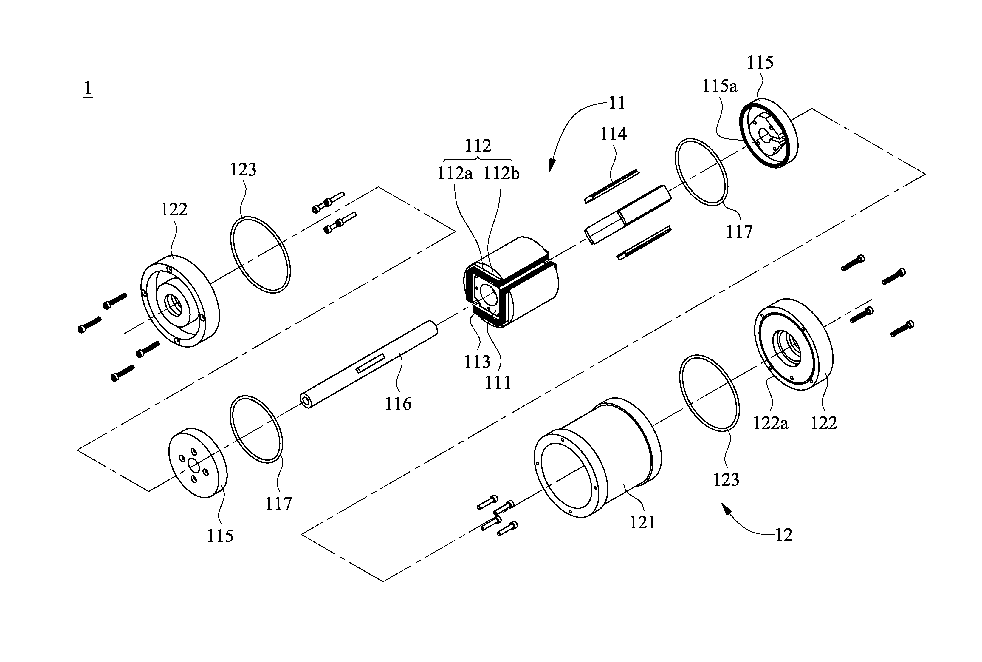
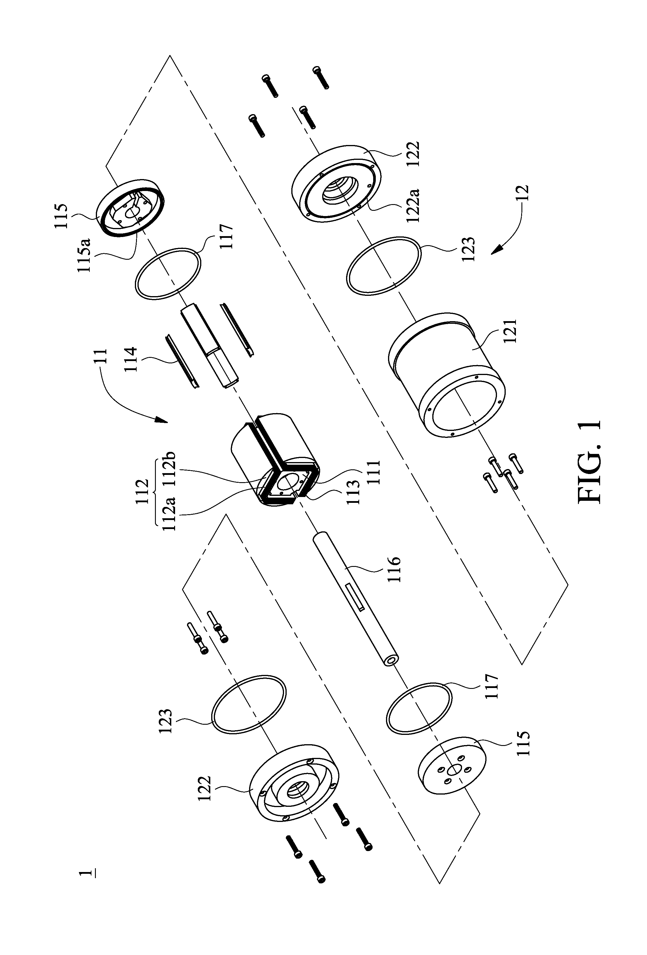
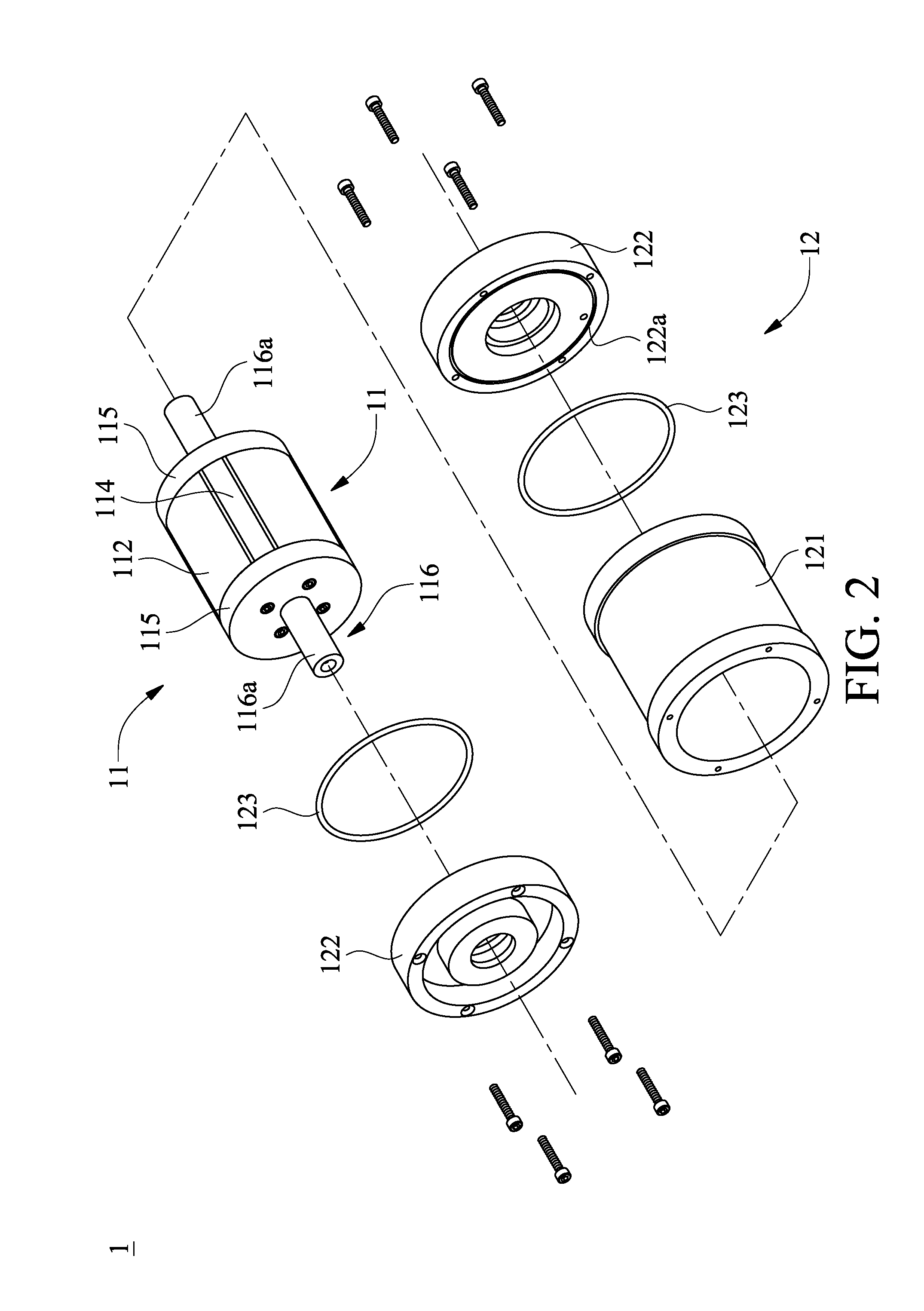
[0023]Please refer to FIGS. 1 to 4, in which FIG. 1 is an exploded perspective view of a rotary resistance device 1 according to a preferred embodiment of the present invention, FIGS. 2 and 3 are partially and fully assembled views, respectively, of the rotary resistance device of FIG. 1, and FIG. 4 is an assembled cross-sectional view of the rotary resistance device of FIG. 1.

[0024]As shown in FIG. 1, the rotary resistance device 1 includes a magnetic field generating assembly 11, a magnetizable outer cylinder 12, and a magnetorheological fluid 13 (see FIG. 4).

[0025]The magnetic field generating assembly 11 includes a magnetizable main body 111, an even number of magnetizable extended bodies 112, an even numbe...


PUM

PropertyMeasurementUnit
magnetic fieldaaaaaaaaaa
magnetizableaaaaaaaaaa
magnetic fieldsaaaaaaaaaa

Abstract

A rotary resistance device providing resistance to rotary object includes a magnetic field generating assembly having a magnetizable main body, an even number of magnetizable extended bodies, magnetizable coils and separators, two first caps, and two shaft sections; a magnetizable outer cylinder enclosing the magnetic field generating assembly therein and rotatably connected to the shaft sections; and a magnetorheological fluid filled in a space formed between the magnetic field generating assembly and the magnetizable outer cylinder. The magnetizable extended bodies have the magnetizable coils wound thereon and are radially equally spaced on the magnetizable main body; the separators are respectively connected to between two adjacent magnetizable extended bodies; the first caps are closed onto two ends of the assembled magnetizable main body, magnetizable extended bodies and separators to seal the magnetizable coils in the magnetic field generating assembly; and the shaft sections are fixedly connected to the first caps.

Description

CROSS-REFERENCE TO RELATED APPLICATION[0001]This non-provisional application claims priority under 35 U.S.C. §119(a) on Patent Application No(s). 103106664 filed in Taiwan, R.O.C. on Feb. 27, 2014, the entire contents of which are hereby incorporated by reference.FIELD OF TECHNOLOGY[0002]The present invention relates to a resistance device, and more particularly to a rotary resistance device that utilizes magnetorheological fluid to provide a resistance to a rotary object.BACKGROUND[0003]A magnetorheological fluid (MRF) is a rapidly developing smart material. When the MRF is subjected to a magnetic field, solid magnetic particles within the MRF are caused to align themselves with the direction of the magnetic lines of force between the N pole and the S pole and accordingly form a plurality of particle chains between the two poles. The formation of the particle chains in the magnetorheological fluid produces an effect of anti-shear stress.[0004]Among the conventional resistance devic...

Claims


Application Information

Patent Timeline
Patent Type & Authority Applications(United States)
IPC IPC(8): H01F5/00
CPCF16D57/002H01F5/00H02K7/10F16D63/002H01F7/20
Inventor SHIAO, YAOJUNGHUANG, GUAN-DA
Owner NAT TAIPEI UNIV OF TECH
Why Eureka
Try Eureka