Roller shutter arrangement more particularly for obliquely arranged roller shutter areas

a roller shutter and arrangement technology, applied in the direction of curtain accessories, curtain suspension devices, building components, etc., can solve the problems of relatively complex and expensive free-wheel and other coupling means, and no longer be able to automatically unwind

Inactive Publication Date: 2000-06-27
SCHANZ HANS
View PDF10 Cites 16 Cited by
  • Summary
  • Abstract
  • Description
  • Claims
  • Application Information

AI Technical Summary

Benefits of technology

One object of the invention is to create a roller shutter arrangement, in the case of which the unwinding operation for the roller shutter element is ensured in a simple and economic manner without the action of gravity.

Problems solved by technology

The more oblique the roller shutter area, the less the action of gravity will be and the greater the effect of friction will be so that for example as from a certain slope automatic unwinding will no longer be possible.
Although arrangements have already been proposed in which the unwinding operation is performed by draw cables, which are also driven by a drive motor, such drive arrangements call for a relatively complex and expensive free-wheel and other coupling means.

Method used


Image

  • Roller shutter arrangement more particularly for obliquely arranged roller shutter areas
  • Roller shutter arrangement more particularly for obliquely arranged roller shutter areas

Examples


Embodiment Construction

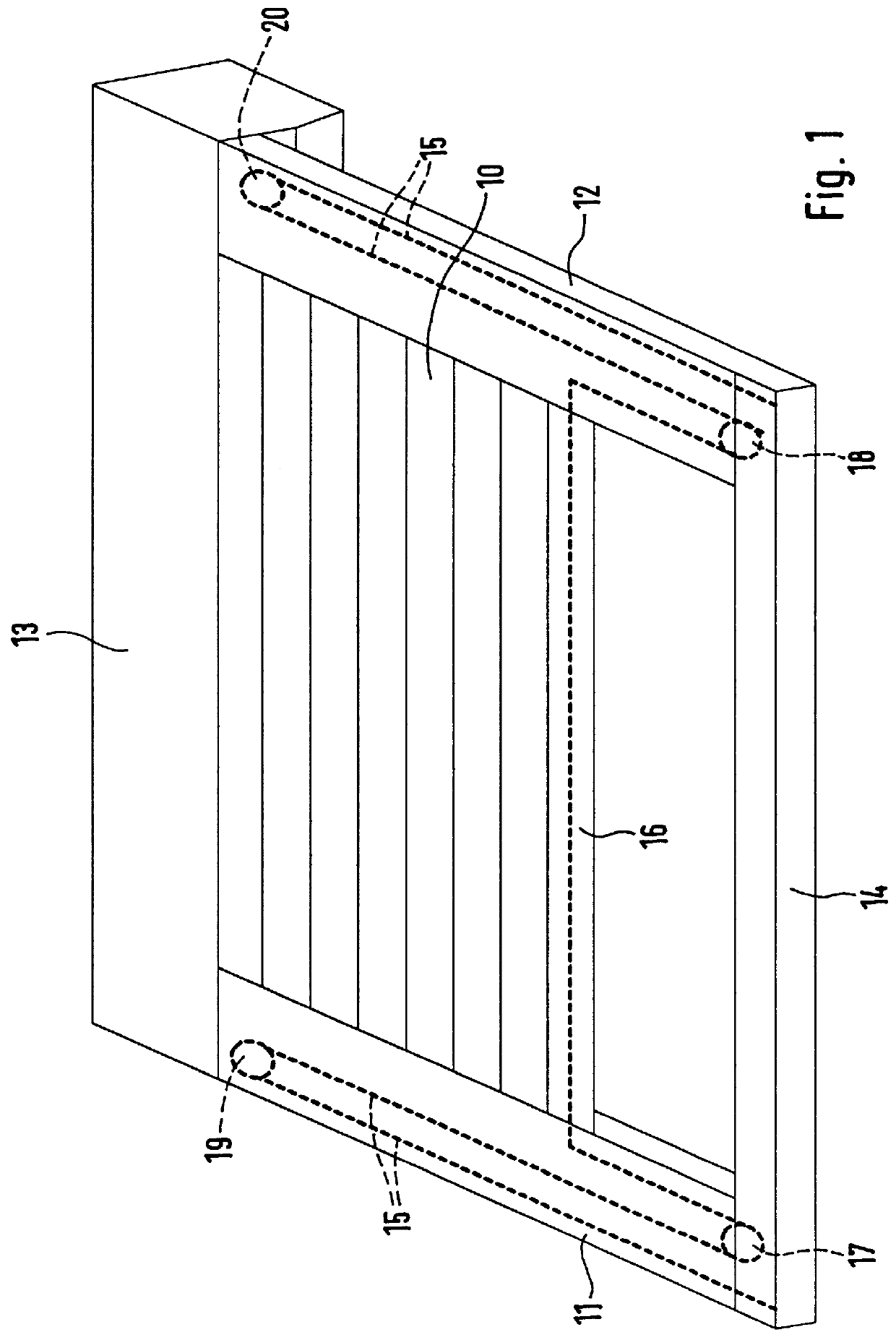
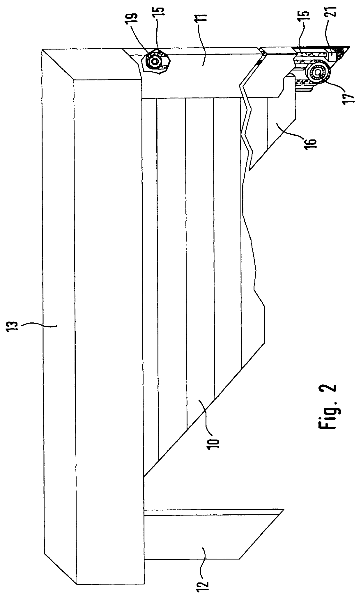
In the case of the embodiment of the invention illustrated in FIGS. 1 and 2 a roller shutter element 10 composed of individual slats runs on two lateral guide rails 11 and 12, of which one end respectively opens into a roller shutter chest 13, in which in a known manner, not described in detail, a take-up shaft is mounted in a rotatable manner for winding up the roller shutter element 10. This take-up shaft may also be provided with an electric drive motor for winding up the roller shutter element 10. As an alternative to this it is also possible for roller shutter webbing to be provided for winding up and unwinding the roller shutter element manually. The opposite end parts of the guide rails 11 and 12 are connected with each other by a connecting rail 14, which represents the terminal abutment for the roller shutter element 10 in the unwound state.

An elastic draw cable 15 runs through the terminal slat 16 at the free end part of the roller shutter element 10. The elastic draw cabl...


PUM


Abstract

A roller shutter arrangement, more especially for obliquely arranged roller shutter areas comprising a roller shutter element running in lateral guide rails and adapted to be wound and unwound on and from a take-up shaft arranged at one end of the roller shutter area. At least one elastic draw cable is provided engaging the free end part of the roller shutter element, and this draw cable is stretched on winding up the roller shutter element on the take-up shaft and on unwinding provides an elastic force aiding the unwinding operation. This means that automatic unwinding of the roller shutter element is possible in a simple and economic manner even if there is an insufficient or no action of gravity.

Description

The invention relates to a roller shutter arrangement more particularly for obliquely arranged roller shutter areas, comprising a roller shutter element running in lateral guide rails and adapted to be wound and unwound on and from a take-up shaft arranged at one end of the roller shutter area.THE PRIOR ARTSuch roller shutter arrangements have been proposed in wide variety of designs. For example in the case of vertical roller shutter arrangements, in which the take-up shaft is arranged above the roller shutter area, the weight force of the roller shutter element is generally sufficient to ensure automatic performance of the unwinding operation, that is to say the roller shutter element is wound up by manual or power rotation of the take-up shaft and on release it will be unwound automatically under its own weight.The more oblique the roller shutter area, the less the action of gravity will be and the greater the effect of friction will be so that for example as from a certain slope...

Claims


Application Information

Patent Timeline
Patent Type & Authority Patents(United States)
IPC IPC(8): E06B9/56E06B9/68E06B9/92
CPCE06B9/92E06B9/68
Inventor SCHANZ, HANS
Owner SCHANZ HANS
Why Eureka
Try Eureka