Method and apparatus for accelerating the cyclic firing rate of a semi-automatic firearm

a semi-automatic firearm and cyclic firing technology, applied in the field of methods and, can solve the problems of inability to afford selective fire, lack of crucial features of the sks carbine, and inability to achieve selective fire, etc., and achieve the effect of accelerating the cyclic firing rate of the semi-automatic version, achieving the effect of accelerating the cyclic firing ra

Inactive Publication Date: 2000-08-15
SLIDE FIRE SOLUTIONS
View PDF8 Cites 68 Cited by
  • Summary
  • Abstract
  • Description
  • Claims
  • Application Information

AI Technical Summary

Problems solved by technology

However, the SKS Carbine lacks a crucial feature that is desired for a military weapon--viz.
: it is incapable of affording selective fire (the ability to operate in either a semi-automatic mode or a fully automatic mode.
Certain "appearanc

Method used


Image

  • Method and apparatus for accelerating the cyclic firing rate of a semi-automatic firearm
  • Method and apparatus for accelerating the cyclic firing rate of a semi-automatic firearm
  • Method and apparatus for accelerating the cyclic firing rate of a semi-automatic firearm

Examples


Embodiment Construction

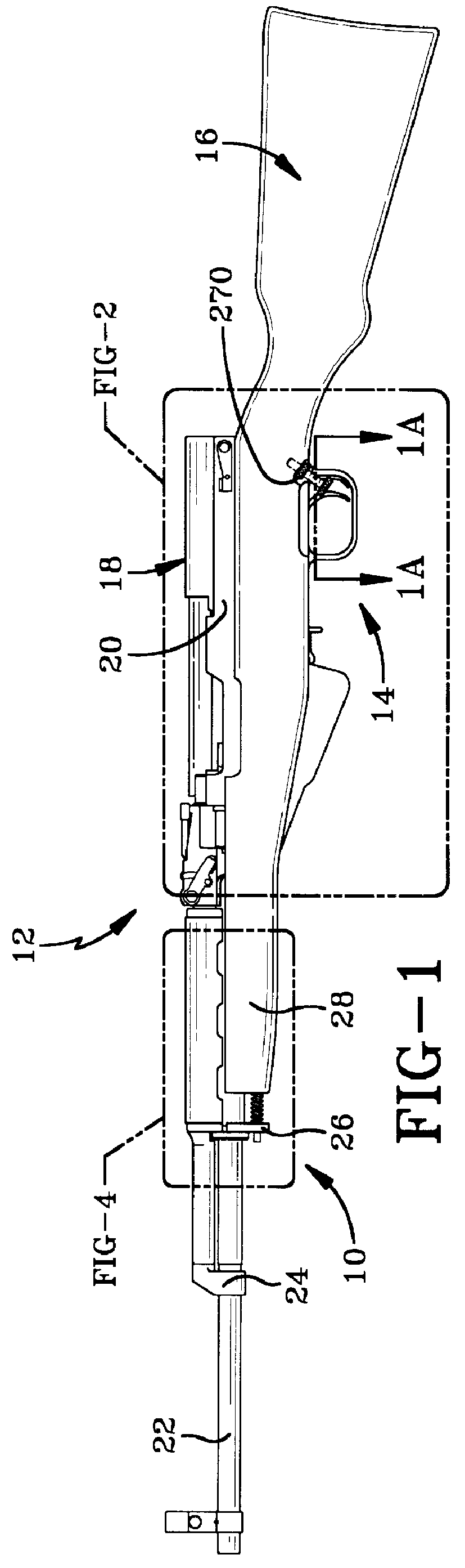
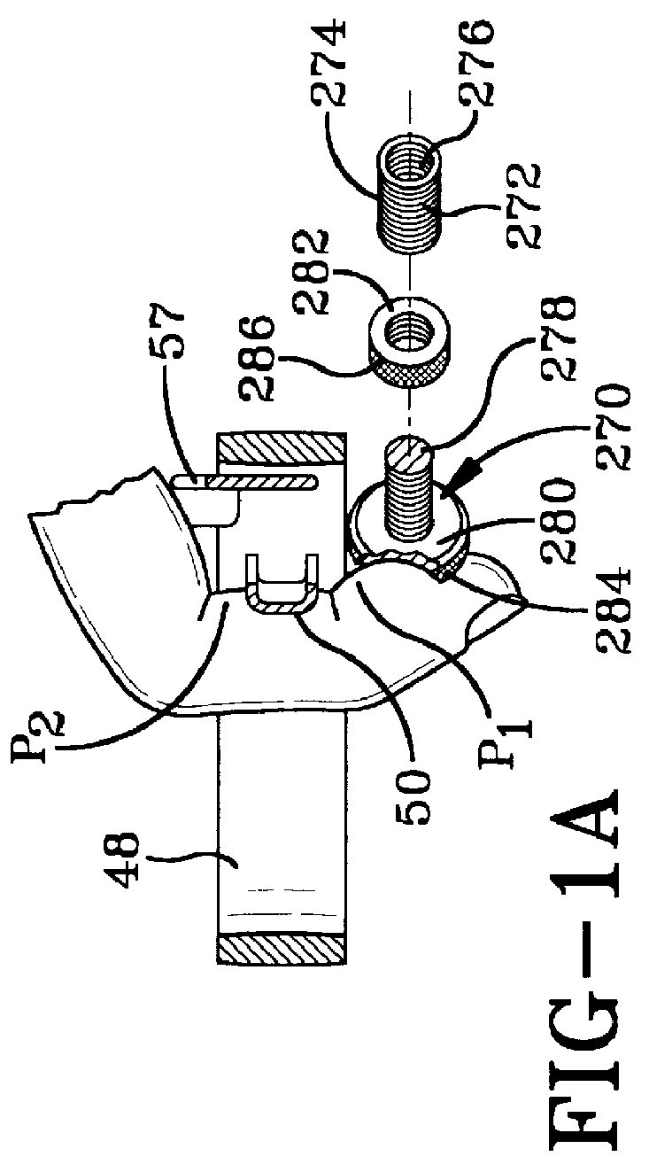
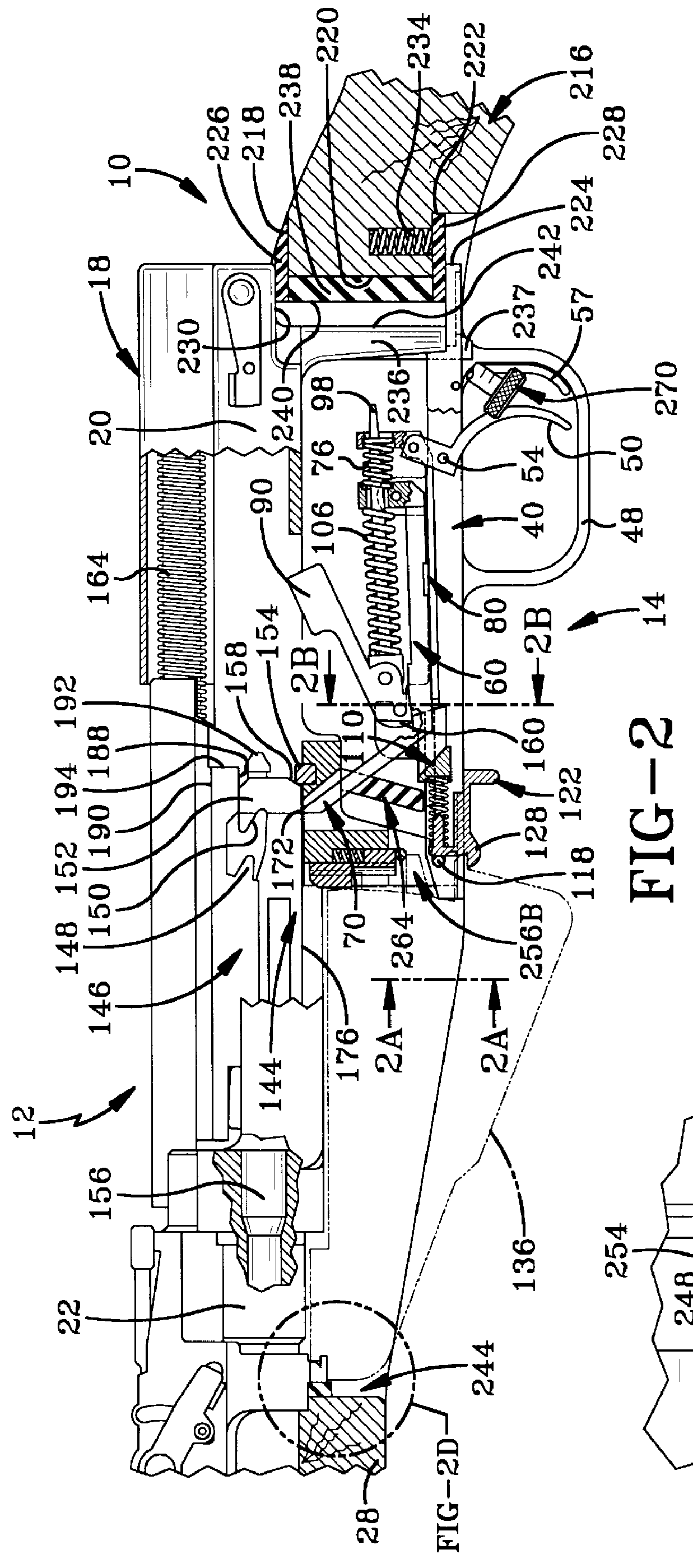
The present invention is directed to a method and apparatus by which to accelerate the cyclic firing rate of a semi-automatic firearm, and as such, the various structural components of one example of such an accelerating assembly are designated generally, and collectively, by the numeral 10 in FIGS. 1 through 6 of the attached drawings. The aforesaid accelerating assembly 10 is depicted in conjunction with an SKS Carbine, the side elevation of which is best seen in FIG. 1 wherein it is designated generally by the numeral 12. The present invention also provides an accelerating assembly adapted for usage with a MAK-90 firearm, it being understood that the two firearms have been selected merely to demonstrate the manner in which various accelerating assemblies can be employed with various semi-automatic firearms, in this instance rifles.

General Background of the SKS Carbine and a MAK-90

The SKS Carbine 12 was selected for several reasons. First, the SKS is a foreign military weapon that...


PUM


Abstract

An accelerating assembly effectively to increase the cyclic rate at which the trigger of a semi-automatic firearm can be actuated to discharge the weapon. The firearm has a supporting device, a receiver housing supported from the supporting device, a trigger and trigger mechanism secured to the receiver housing. The accelerating mechanism incorporates structure that permits the receiver and the trigger to translate rearwardly a predetermined distance with respect to the supporting device in response to the recoil imparted by the discharge of the semi-automatic firearm. A biasing arrangement continuously urges the receiver, and trigger, to translate forwardly with respect to the supporting device substantially that same predetermined distance. A locating stop is mounted on the supporting device. The locating stop is disposed to be engaged by the shooter's finger after the trigger has been actuated to fire the semi-automatic weapon. That engagement of the shooter's trigger finger with the locating stop effectively immobilizing the shooter's trigger finger with respect to the supporting device until the shooter releases the trigger. The method of the present invention operates by depressing the trigger with a shooter's trigger finger in order to discharge the firearm. The shooter's finger is then immobilized in the position it has assumed to discharge the firearm. The trigger is translated away from the immobilized trigger finger to effect a total disengagement therebetween. Sequentially thereafter the trigger is biased into engagement with the immobilized trigger finger to effect successive discharges of the firearm.

Description

The present invention relates generally to firearms. More particularly, the present invention relates to methods and structural arrangements by which to accelerate the cyclic firing rate of a semi-automatic firearm. Specifically, the present invention relates to a method and apparatus which accelerates the cyclic firing rate of a semi-automatic firearm by moving the trigger successively into and out of contact with the shooter's trigger finger while maintaining the butt of the stock in firm, uninterrupted contact with the shooter's shoulder. Accordingly, the trigger finger disengages the trigger for each successive firing, insuring the preservation of the semi-automatic action and its mechanism.Although today's media inaccurately, and irresponsibly, designate semi-automatic firearms as being "automatic" weapons, one must not lose sight of the fact that there is a significant distinction between a semi-automatic and an automatic (perhaps, more accurately, a "fully automatic") firearm...

Claims


Application Information

Patent Timeline
IPC IPC(8): F41A19/03F41A19/00F41A25/24F41A19/10F41A25/00
CPCF41A19/03F41A19/10F41A25/24
Inventor AKINS, WILLIAM
Owner SLIDE FIRE SOLUTIONS
Why Eureka
Try Eureka