Eureka AIR delivers breakthrough ideas for toughest innovation challenges, trusted by R&D personnel around the world.

Rate control mechanism

a rate control and rate technology, applied in the direction of firing/trigger mechanism, weapon components, weapons, etc., can solve the problems of uncontrollable weapon movement off target, serious safety hazards for fellow soldiers and bystanders, and the natural cyclic rate of a firearm may not be the optimal cyclic rate, so as to reduce the cyclic rate of a self-powered firearm

Inactive Publication Date: 2014-12-02
REYNOLDS S PAUL +1
View PDF13 Cites 14 Cited by
  • Summary
  • Abstract
  • Description
  • Claims
  • Application Information

AI Technical Summary

Benefits of technology

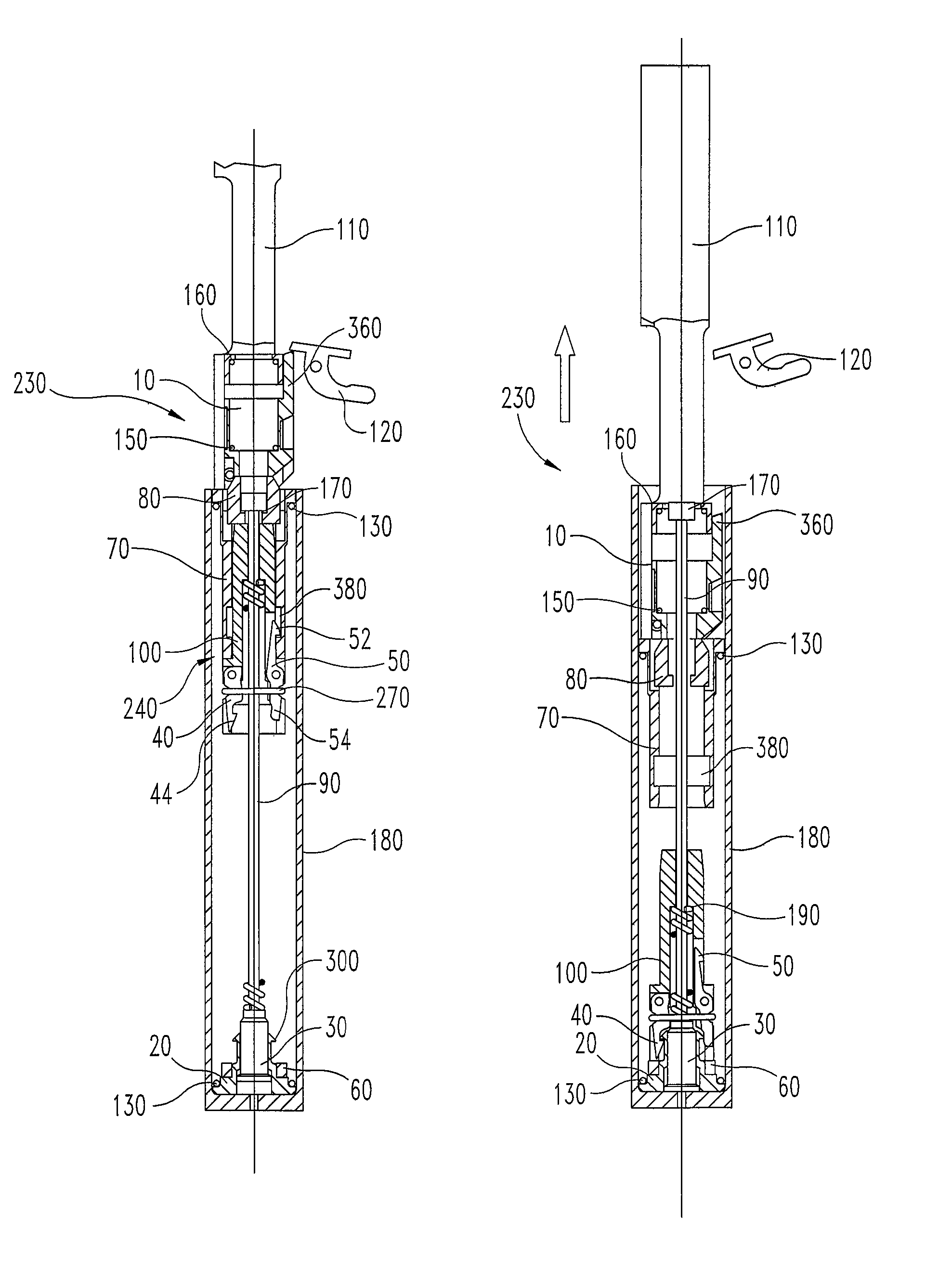
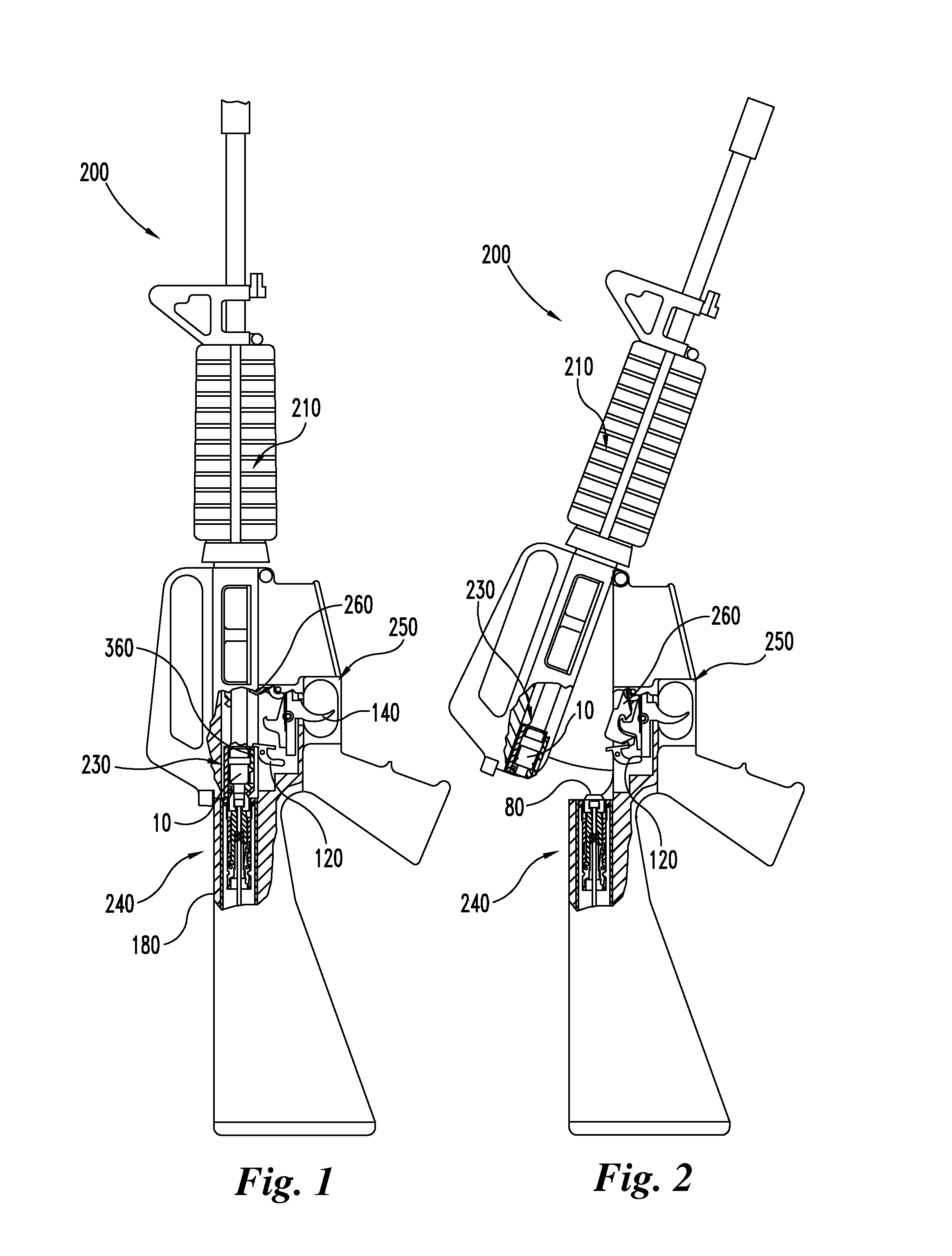
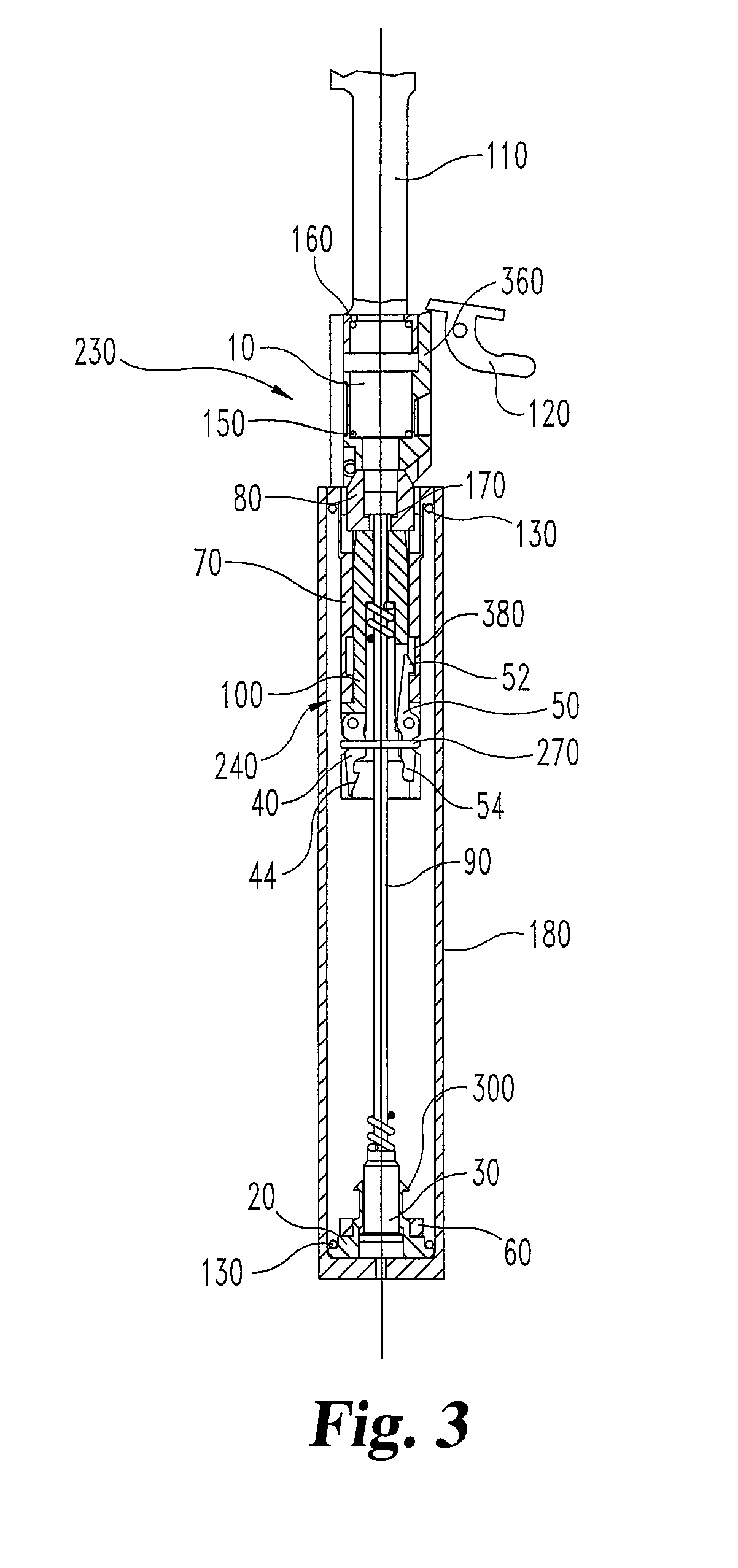
[0008]In certain embodiments, a method is disclosed for reducing the cyclic rate of a self-powered firearm. The method includes allowing a timing group assembly to travel rearward relative to a pull rod within a receiver extension of a self-powered firearm upon an initial recoil action. An inertia weight of the timing group assembly is retained at a rearward position within the receiver extension while disengaging the inertia weight from the remainder of the timing group. The remainder of the timing group is urged to travel forward relative to the pull rod, causing the pull rod to advance and to disengage the inertia weight from the rearward end of the receiver extension. The disengaged inertia weight is urged to travel forward within the receiver extension; and, allowed to travel forward to an impact position wherein the inertia weight communicates force forward sufficient to actuate a sear to fire the firearm.

Problems solved by technology

Unfortunately, the natural cyclic rate of a firearm may not be the optimum cyclic rate for the target engagement scenarios most commonly encountered.
Most shoulder-fired fully automatic firearms such as the M16 family of rifles and the M4 family of carbines have such high natural cyclic rates of fire that the rapidly delivered recoil impulses to the shooter cause the weapon to move off target uncontrollably.
This not only reduces hit probability, but wastes ammunition, overheats and rapidly wears out mechanical aspects such as barrels, can cause a serious safety hazard to fellow soldiers and bystanders, and reduces “trigger time” for the available ammunition.
This makes target reacquisition time consuming / difficult.
The uncontrollability of the M4 Carbine (which is typical of current military rifles and carbines) in full automatic fire also contributes to wastage of ammunition, excess barrel heating, etc.
Rifles having heavier recoil than the 5.56 mm NATO Cartridge (such as those chambered for 7.62 mm NATO) greatly exacerbate the controllability problem.
Three round burst limiters do not so much provide increased hit probability, but rather provide more trigger time / pulls per magazine.
The amount of rate reduction achievable using hydraulic buffers is limited because the recoiling parts themselves are slowed, and the firearm cannot function at all below a certain operating mechanism velocity.
This is because the minimum amount of momentum required to carry the recoiling parts through the cycle of functioning is lost.
The U.S. military, as well as civilian industry, have developed several hydraulically based rate reducing mechanisms for the M16 / M4 family of weapons; however, hydraulic rate control mechanisms do not achieve an effective reduction in cyclic rate.
While this slowing results in somewhat reducing the cyclic rate, it also results in reduced functional reliability because energy is removed that is required for reliably cycling the mechanism.
Additionally, hydraulic buffers react unfavorably to extreme hot and cold environments; delivering less rate reduction in high temperature environments and being sluggish at cold temperatures.
The largest disadvantage, however, with hydraulic systems is their inherent inability to adequately reduce the cyclic rate sufficiently to substantially increase hit probability.

Method used


Image

  • Rate control mechanism
  • Rate control mechanism
  • Rate control mechanism

Examples


Embodiment Construction

[0046]For the purposes of promoting an understanding of the principles of the disclosure, reference will now be made to the embodiments illustrated in the drawings and specific language will be used to describe the same. It will nevertheless be understood that no limitation of the scope of the invention is thereby intended, such alterations and further modifications in the illustrated device, and such further applications of the principles of the invention as illustrated therein being contemplated, as would normally occur to one skilled in the art to which the invention relates.

[0047]Embodiments of the present disclosure incorporate a “rate reducer,” namely a cyclic rate reducing mechanism applicable to the M16 / M4 family of weapons in particular. While described in the context of an M16 / M4 type of system, the rate reducer can be readily scaled to be applicable for larger caliber M16 style firearms, as well as being applicable to other weapons employing similar operating systems, and...


PUM


Abstract

Certain embodiments disclose rate reducer systems and methods to reduce the cyclic rate of self-powered firearms. The reduction in cyclic rate is achieved by mechanically delaying the firing step in the cycle of functioning. This delay is achieved by temporarily latching an inertia weight at the rear of the recoil stroke while the recoiling parts return to battery (i.e. a firing position). When the recoiling parts go into battery, the inertia weight is released and urged forward. At the forward end of its travel, the inertia weight actuates the firing mechanism.

Description

BACKGROUND OF THE INVENTION[0001]All self-powered firearms have a natural cyclic rate. The natural cyclic rate of each firearm is a function of its design so the natural cyclic rate is merely an outcome of the design. Unfortunately, the natural cyclic rate of a firearm may not be the optimum cyclic rate for the target engagement scenarios most commonly encountered. Generally speaking, the natural cyclic rate of firearms intended for antipersonnel use is far higher than would be optimum. The cyclic rate of a firearm is usually expressed as the number of Shots Per Minute (spm) that the firearm would discharge when fired in the fully automatic mode, although in actual practice firearms are seldom fired continuously for one minute.[0002]Most shoulder-fired fully automatic firearms such as the M16 family of rifles and the M4 family of carbines have such high natural cyclic rates of fire that the rapidly delivered recoil impulses to the shooter cause the weapon to move off target uncontro...

Claims


Application Information

Patent Timeline
Patent Type & Authority Patents(United States)
IPC IPC(8): F41A3/54F41A5/12
CPCF41A3/78F41A19/03F41A5/12
Inventor REYNOLDS, GEORGE L.REYNOLDS, S. PAUL
Owner REYNOLDS S PAUL
Why Eureka
Eureka Blog
Learn More