Fixed bed reactor

A fixed bed reactor and reaction gas technology, applied in chemical instruments and methods, inorganic chemistry, non-metallic elements, etc., can solve the problems of high cost, difficult to large-scale, difficult catalyst filling, limited tube sheet space, etc., and achieve reaction temperature control. Uniformity, reducing process air resistance, and large circulation rate

Pending Publication Date: 2021-06-11
张晓艳
View PDF3 Cites 3 Cited by
  • Summary
  • Abstract
  • Description
  • Claims
  • Application Information

AI Technical Summary

Problems solved by technology

[0003] The patent disclosed as CN103435006B and titled "A High CO High Conversion Rate Isothermal Shift Reactor and Its Process" adopts the upper and lower layers of tube sheets as large as the shell, which not only has the problem of high cost and difficulty in large-scale, And because many catalyst filling ports need to be opened on the two-layer flat tube sheet, these filling ports need to be opened when loading the catalyst, and then need to be covered after filling, which makes it extremely difficult to load the catalyst; in addition, if the heat exchange tube leaks, it must be taken out. , and the lower two layers of large tube sheets can be repaired and plugged
[0004] The publication number is CN207153662U, the patent titled "a kind of isothermal shift furnace", and the patent publication number is CN203227477U, the title is "a kind of isothermal fixed bed reactor with catalyst installed between the heat exchange tubes", all adopt multiple There are two upper tube sheets and one lower tube sheet, the structure is complex, and since multiple upper and lower tube sheets are used, the space between the tube sheets is limited, and it is impossible for operators to directly enter the tube sheet, so they can only take out the internal parts. In the case of leakage, repair and plug the leak

Method used


Image

  • Fixed bed reactor
  • Fixed bed reactor
  • Fixed bed reactor

Examples


Embodiment Construction

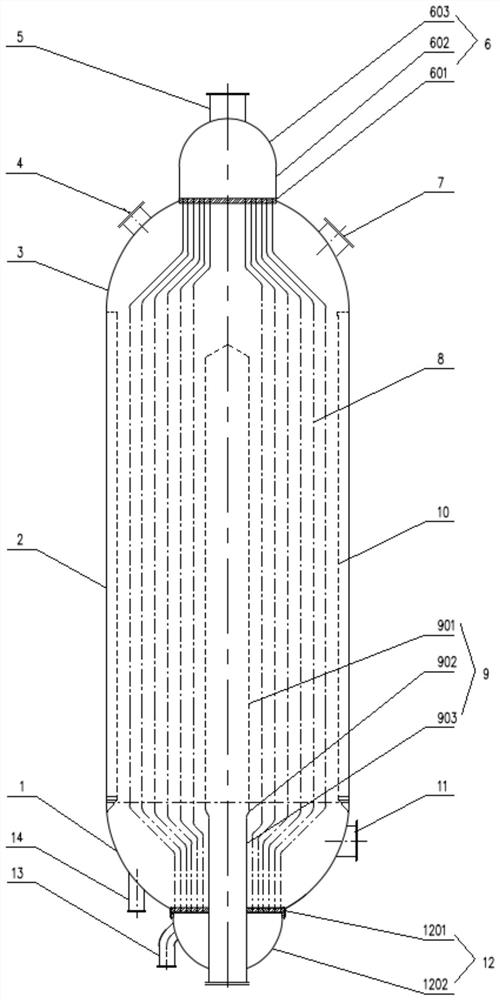
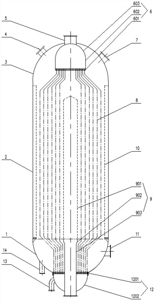
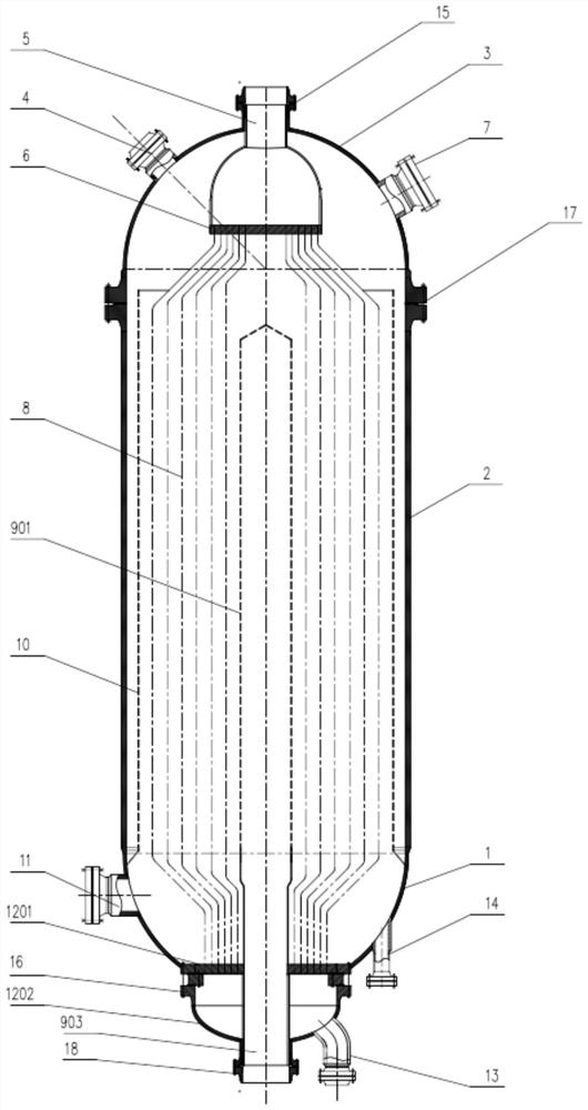
[0024] According to the requirements of GB151 shell and tube heat exchanger, the center distance of heat exchange tubes should not be less than 1.25 times the outer diameter of heat exchange tubes. The center distance of commonly used heat exchange tubes is between 1.25 and 1.3 times the outer diameter of heat exchange tubes. The reactor used for heat transfer and heat transfer needs to be filled with catalyst between the heat exchange tubes, so the distance between the heat exchange tube layers is more than twice the outer diameter of the heat exchange tubes, so the tube sheet with a smaller radial dimension than the shell can be used To arrange the number of heat exchange tubes that meet the heat transfer requirements, and the heat exchange tubes are bent to fill the shell. Another advantage of using a tube sheet smaller than the radial dimension of the shell is that the space outside the tube sheet can be used to arrange the loading and unloading ports of the catalyst and th...


PUM


Abstract

The present invention discloses a fixed bed reactor. The fixed bed reactor comprises a shell, the shell comprises: a straight cylinder (2), a lower sealing head (1) and an upper sealing head (3), wherein the upper sealing head is provided with a reaction gas inlet (4) and a charging port (7), and the lower sealing head is provided with a manhole (11) and a discharging port (14); a lower pipe box (12) which is connected with one end, far away from the straight cylinder, of the lower sealing head and is provided with a hot water inlet connecting pipe (13); an upper tube box (6) which is connected with one end, far away from the straight cylinder, of the upper sealing head and is provided with a steam-water mixture outlet connecting tube (5); a heat exchange tube bundle (8), wherein heat exchange tubes of the heat exchange tube bundle (8) are fixed and communicated with the tube plates of the upper tube box, and the lower tube box, and the diameter of the tube plate of the upper tube box and the diameter of the tube plate of the lower tube box are smaller than the diameter of the shell; a central pipe which is used for collecting and discharging reacted gas; and a catalyst frame. According to the reactor disclosed by the invention, the heat exchange tubes can be checked and plugged without taking out internal parts, and loading and unloading of a catalyst are not hindered; and the large-angle arched heat exchange pipe is small in water circulation resistance, and reaction heat can be quickly removed.

Description

technical field [0001] The application belongs to the field of gas-solid phase reactors, in particular to fixed bed reactors. Background technique [0002] The carbon monoxide shift reactor is a widely used reactor in the petroleum and coal chemical industry. After years of development, it has developed from an adiabatic reactor to an isothermal transfer heat reactor. In the isothermal transfer heat reactor, a heat exchange tube is installed in the shell, and the heat generated by the carbon monoxide shift reaction is removed in time through the water in the heat exchange tube to realize the "isothermal" reaction. But there are many problems in the existing isothermal reactor. [0003] The patent disclosed as CN103435006B and titled "A High CO High Conversion Rate Isothermal Shift Reactor and Its Process" adopts the upper and lower layers of tube sheets as large as the shell, which not only has the problem of high cost and difficulty in large-scale, And because many cataly...

Claims


Application Information

Patent Timeline
Patent Type & Authority Applications(China)
IPC IPC(8): B01J8/06C01B3/16
CPCB01J8/06B01J8/067C01B3/16
Inventor 张晓艳张天翼
Owner 张晓艳
Why Eureka
Try Eureka