Electrosurgical instrument

a surgical instrument and electrosurgical technology, applied in the field of electrosurgical instruments, can solve the problems of increasing the manufacturing cost of the electrosurgical endoscopic instrument and/or increasing production, increasing the cost of cam pin uncoupling, and the electrosurgical endoscopic device not functioning as intended, so as to facilitate the movement of at least one movable jaw member, the effect of reducing the drag for

Active Publication Date: 2015-02-24
TYCO HEALTHCARE GRP LP
View PDF137 Cites 247 Cited by
  • Summary
  • Abstract
  • Description
  • Claims
  • Application Information

AI Technical Summary

Benefits of technology

[0009]According to an aspect of the present disclosure, the drive rod and the elongated channel are in horizontal registration with one another to facilitate moving the at least one movable jaw member from the open configuration to the clamping configuration. The drive rod may include a generally rounded distal end to reduce a drag force thereagainst during distal translation of the drive rod within the elongated channel. The drive rod may be positioned above a pivot pin that couples the first and second jaw members.

Problems solved by technology

As can be appreciated, forming a drive rod with a cam pin and, subsequently, positioning the cam pin within the one or more cam slots on the jaw members may increase manufacturing costs of the electrosurgical endoscopic instrument and / or increase production.
Moreover, and in the instance where the cam pin is not integrally formed with the drive rod, e.g., soldering is used to join the cam pin to the drive rod, there exists the likelihood of the cam pin uncoupling from the drive rod during use thereof, which, in turn, may result in the electrosurgical endoscopic device not functioning as intended.
As can be appreciated, having to add the resilient member to the electrosurgical endoscopic instrument may further increase manufacturing costs of the electrosurgical endoscopic instrument and / or increase production time of the electrosurgical endoscopic instrument.

Method used


Image

  • Electrosurgical instrument
  • Electrosurgical instrument
  • Electrosurgical instrument

Examples


Embodiment Construction

[0021]Detailed embodiments of the present disclosure are disclosed herein; however, the disclosed embodiments are merely examples of the disclosure, which may be embodied in various forms. Therefore, specific structural and functional details disclosed herein are not to be interpreted as limiting, but merely as a basis for the claims and as a representative basis for teaching one skilled in the art to variously employ the present disclosure in virtually any appropriately detailed structure.

[0022]Embodiments of the present disclosure are described in detail with reference to the drawing figures wherein like reference numerals identify similar or identical elements. As used herein, the term “distal” refers to the portion that is being described which is further from a user, while the term “proximal” refers to the portion that is being described which is closer to a user.

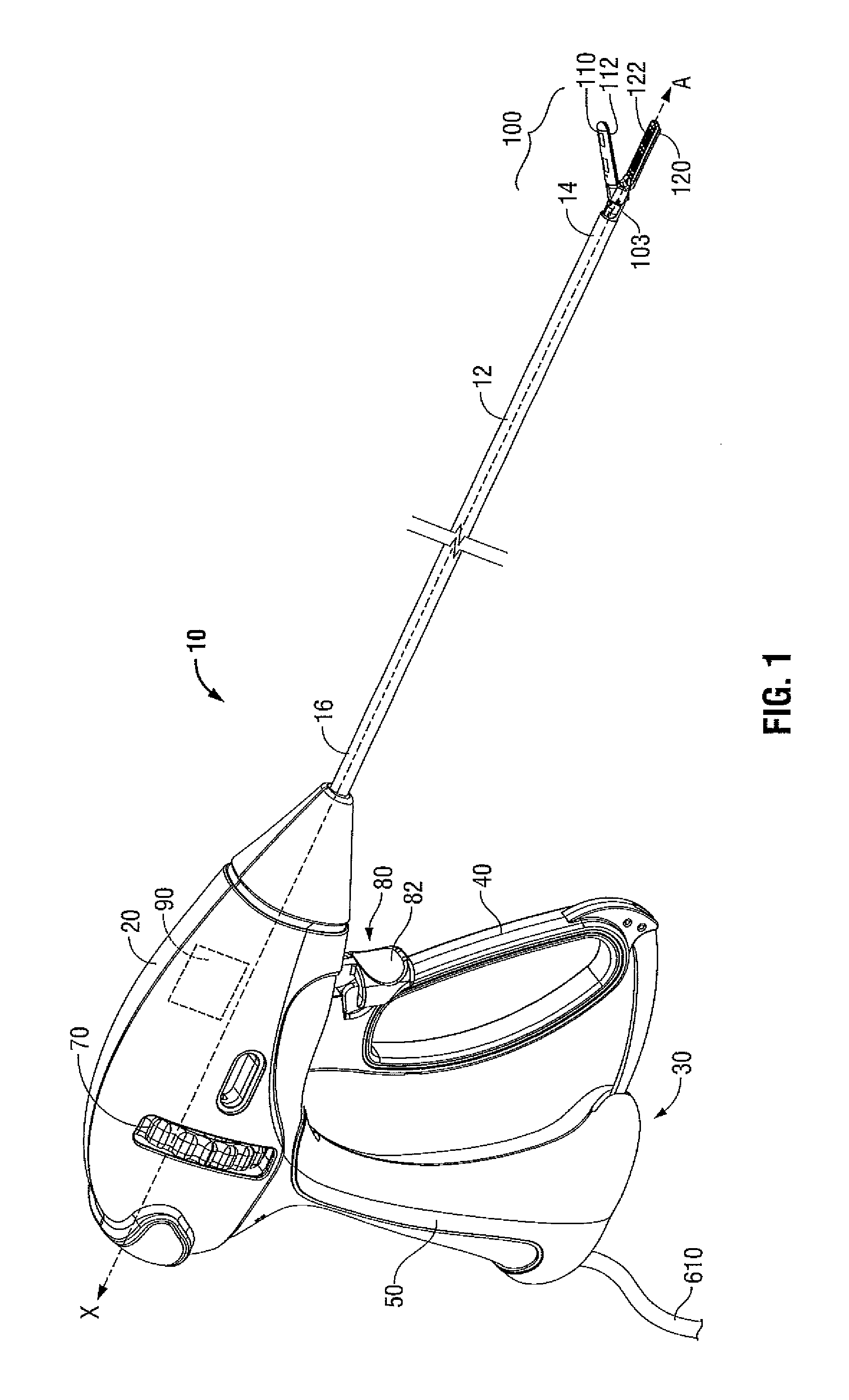
[0023]Turning now to FIG. 1, an electrosurgical endoscopic forceps 10 (forceps 10) is provided having a longitudinal...


PUM


Abstract

An electrosurgical forceps is provided with a shaft that extends from a housing of the electrosurgical forceps. An end effector assembly operably coupled to a distal end of the shaft includes a pair of first and second jaw members each having jaw housing and an electrosurgical seal plate. One or both of the first and second jaw members is movable from an open configuration, to a clamping configuration. The moveable jaw member includes an elongated channel defined in its respective jaw housing and extends along a length thereof. A drive assembly operably couples to the moveable jaw member via a drive rod that is engageable with the elongated channel to move the movable jaw member from the open configuration to the clamping configuration and to provide a closure force between the first and second jaw members when the jaw members are in the clamping configuration.

Description

BACKGROUND[0001]1. Technical Field[0002]The present disclosure relates to an electrosurgical instrument and, more particularly, to an electrosurgical instrument including a drive assembly in operable communication with an end effector to effect movement of one or both of a pair of jaw members from a spaced-apart configuration to a closed or clamping position.[0003]2. Description of Related Art[0004]Electrosurgical forceps are well known in the medical arts. For example, an electrosurgical endoscopic forceps is utilized in surgical procedures, e.g., laparoscopic surgical procedures, where access to tissue is accomplished through a cannula or other suitable device positioned in an opening on a patient. The endoscopic forceps, typically, includes a housing, a handle assembly including a movable handle, a drive assembly, a shaft and an end effector assembly attached to a distal end of the shaft. The end effector includes jaw members that operably communicate with the drive assembly to m...

Claims


Application Information

Patent Timeline
Patent Type & Authority Patents(United States)
IPC IPC(8): A61B17/00A61B18/14A61B17/29
CPCA61B18/1445A61B2018/1455A61B2017/2932A61B2017/2933A61B17/29A61B18/085A61B2018/00595
Inventor TWOMEY, JOHN R.ALLEN, IV, JAMES D.CHOJIN, EDWARD M.KINGSLEY, DYLAN R.UNGER, JEFFREY R.
Owner TYCO HEALTHCARE GRP LP
Why Eureka
Try Eureka