Rotator compressor

A compressor and rotor type technology, applied in the field of compressors, can solve problems such as the decline of lubrication, sealing and cooling effects, and achieve the effects of reducing contact, preventing excessive sag, and improving performance

Active Publication Date: 2016-11-16
GREE ELECTRIC APPLIANCES INC
View PDF9 Cites 3 Cited by
  • Summary
  • Abstract
  • Description
  • Claims
  • Application Information

AI Technical Summary

Problems solved by technology

[0005] Therefore, the technical problem to be solved by the present invention is to overcome the defect that the lubricating, sealing and cooling effect of the rotary compressor in the prior art is reduced, thereby providing a rotary compressor

Method used


Image

  • Rotator compressor
  • Rotator compressor
  • Rotator compressor

Examples


Embodiment Construction

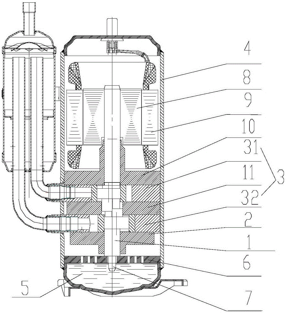
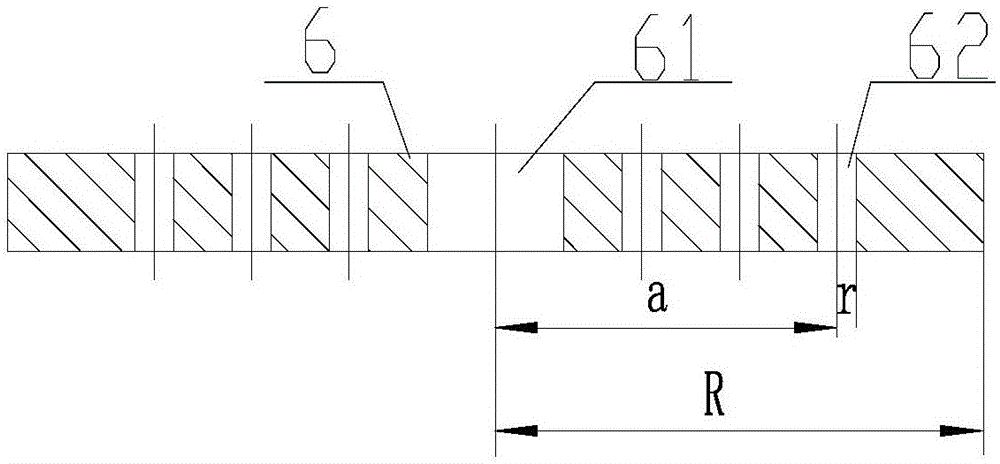
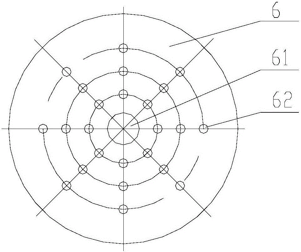
[0030] Such as Figure 1-3 As shown, the present invention provides a rotary compressor, which includes a crankshaft 1, a lower flange 2, a cylinder 3 (including an upper cylinder 31 and a lower cylinder 32) and a housing 4, and is arranged at the inner bottom of the housing 4 The oil pool 5, wherein an oil retaining structure is also provided between the lower flange 2 and the bottom of the housing 4, and the oil retaining structure extends from the central axis position of the crankshaft 1 along its radial direction to a position close to the side wall of the housing 4 .

[0031] In the rotor compressor of the present invention, an oil retaining structure is provided between the lower flange and the bottom of the housing, and the oil retaining structure extends from the position of the central axis of the crankshaft along its radial direction to close to the side wall of the housing The position can prevent the oil in the oil pool near the side wall of the housing from flow...


PUM


Abstract

The invention provides a rotator compressor. The rotator compressor comprises a crank shaft (1), a lower flange (2), a cylinder (3), a shell (4), and an oil pool (5) arranged at the inner bottom of the shell (4), wherein an oil blocking structure is arranged between the lower flange (2) and the bottom of the shell (4); and the oil blocking structure extends from the central axis position of the crank shaft (1) to the position near the side wall of the shell (4). According to the rotator compressor, the oil blocking structure is arranged between the lower flange and the bottom of the shell, so that the situation that the oil level in the position near the inner wall of the shell rises due to a centrifugal action generated through rotation driving of the crank shaft can be effectively prevented, the situation that the central oil level sinks too much due to the centrifugal action is effectively prevented, the central oil level is prevented from dropping too low, the purpose that the crank shaft can always suck oil from the oil pool is guaranteed, and the technical problem that lubricating, sealing and cooling functions of the compressor are decreased due to the fact that the crank shaft is short and stirs the oil is overcome.

Description

technical field [0001] The invention belongs to the technical field of compressors, and in particular relates to a rotor compressor. Background technique [0002] In the prior art, when the compressor starts, the crankshaft rotates at a high speed, the short shaft of the crankshaft and its connected oil suction pipe extend into the oil pool to stir the oil, the lubricating oil is under the action of centrifugal force, and the oil level near the rotation center of the crankshaft is concave, The oil level near the casing rises, making it difficult for the crankshaft to absorb oil, reducing the lubrication effect. Restricting the length of the short shaft of the crankshaft can reduce the agitation of the oil, but the oil suction pipe connected to it still has the problem of disturbing the oil, resulting in an unstable oil level and an excessively concave center oil surface. [0003] The patent No. 201020695491.3 in the prior art provides a short-shaft shield for a rotor compre...

Claims


Application Information

Patent Timeline
IPC IPC(8): F04C29/02
CPCF04C29/02F04C29/028
Inventor 向柳阙沛祯胡艳军翟元彬黄建峰
Owner GREE ELECTRIC APPLIANCES INC
Why Eureka
Try Eureka