Omni-directional antenna system for wireless communication

a wireless communication and omni-directional technology, applied in the structural form of the antenna, the the structure of the antenna, etc., can solve the problems of reducing affecting the service life of the user, so as to reduce the loss and reduce the exposure of the user

Inactive Publication Date: 2012-02-16
KAONETICS TECH
View PDF7 Cites 183 Cited by
  • Summary
  • Abstract
  • Description
  • Claims
  • Application Information

AI Technical Summary

Benefits of technology

[0027]In yet another example of the present invention, the antenna system further comprises a coaxial cable extending from the lead connecting the power amplifier to ground toward the floating ground plane, and the end of the coaxial cable is preferably no more than ten (10) mm from the floating ground plane. The length of the coaxial cable extending toward the floating ground plane may be about one and a half (1.5) centimeters to about three and a half (3.5) centimeters long and preferably as short as possible to reduce losses. Other lengths for the coaxial cable extending toward and in proximity to the floating ground plane from the lead that connects the power amplifier to ground is contemplated.
[0028]In a further embodiment of the invention which advantageously reduces a user's exposure to the radiation effects of the wireless device, particularly the radiation exposure to the head of the user, an antenna and a floating ground plane is provided, preferably a circularly polarized antenna and a conductive floating ground plane, whereby the floating ground plane is positioned and configured to inductively couple the floating ground plane to the antenna and the user is capacitively coupled to the wireless device by contacting the floating ground plane or a conductive member or conductive contact electrically connected to the floating plane so that the user becomes part of the antenna. It is believed that when the user is coupled to the antenna and becomes part of the antenna, there is less concentration of the electromagnetic signal at the head and / or ear of a user and that the signal is propagated away from the head. It is believed that in this embodiment, the direction of propagation of the signal is changed and directed away from the head of the user. In one embodiment, the floating ground plane is positioned and configured to lie substantially over and preferably cover entirely one side of the antenna. It is believed that the electromagnetic waves transmitted by the wireless device are propagated and dispersed away from the user by the floating ground plane. For example, in a wireless or mobile phone, the antenna and the floating ground plane may be positioned advantageously closer to the (back) side of the phone that is away from the user, and the user of the wireless or mobile phone preferably handles the phone so that the other opposite (front) side is directed toward their body. The floating ground plane preferably substantially or entirely covers, overlies or overlaps the area of the antenna so that the electromagnetic waves are believed to be propagated away from the user. In one embodiment the antenna components of the circularly polarized antenna preferably comprising the radiating element and the antenna ground are formed on a first or front side of a printed circuit board and a metallic sheet, foil or plate is placed over and substantially covers the majority of the second or back side of the printed circuit board, and the printed circuit board assembly is positioned in the wireless device toward the back side of the wireless device and preferably over the battery pack so that the antenna components face the battery pack and the front of the housing.
[0029]An optional audio output device, e.g., a speaker, may be located in the mobile or wireless device preferably between the floating ground plane and the front side of the device, and preferably located so as to transmit sound toward the first side, while the floating ground plane protects the user from exposure to electromagnetic radiation transmitted and received by the antenna of the wireless device by propagating the signal away from the user, and dispersing and distributing the signal over the entire user as the user becomes part of the antenna system.

Problems solved by technology

Conventional antennas inclusive of television, radio, GPS, wireless routers, WiFi, wireless and cellular phones, typically experience signal loss due to attenuation.
In such situations the signal can be interrupted by material obstructions, such as, for example, buildings, mountains and other obstructions, that interfere with the straight line of sight communication of the wireless devices.
For a mobile, cellular or wireless phone, signal loss also typically occurs when your hand or other body parts attenuate on sensitive parts of the mobile phone's antenna.
This may cause the antenna in the lower left corner of the phone housing to become detuned which reduces the data transfer rate.
Other problems with conventional antennas and the transmission and reception of radio frequencies, including microwave frequencies, is that interference between propagating signal waves can cause wave cancellation and can result in loss of signal strength.
This wave cancellation and loss of signal strength can result from a signal wave interfering with itself as a result of reflecting off of surfaces and self-cancelling, or may result from a separate signal source.
Because of this wave cancellation problem, cell phone towers, WiFi spots, radio and television broadcasts, jammers, and other communication devices are subject to signal loss and avoid overlapping coverage areas.
Further problems in connection with mobile phones and other wireless technology include the radiation and health effects of being exposed to electromagnetic radiation, and in particular high frequency radio and microwaves associated with mobile phones, especially when these devices are used so close to the human body, and in particular the head of the human body.

Method used


Image

  • Omni-directional antenna system for wireless communication
  • Omni-directional antenna system for wireless communication
  • Omni-directional antenna system for wireless communication

Examples


example 1

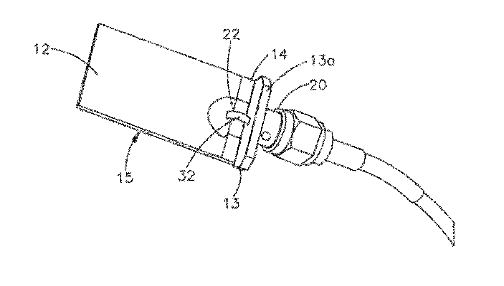
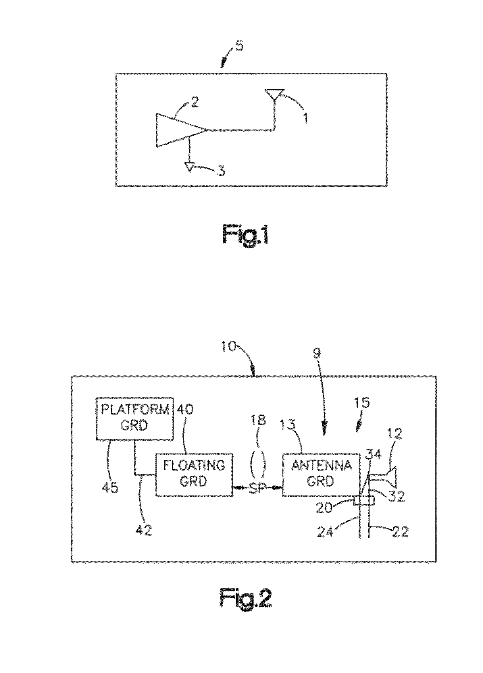
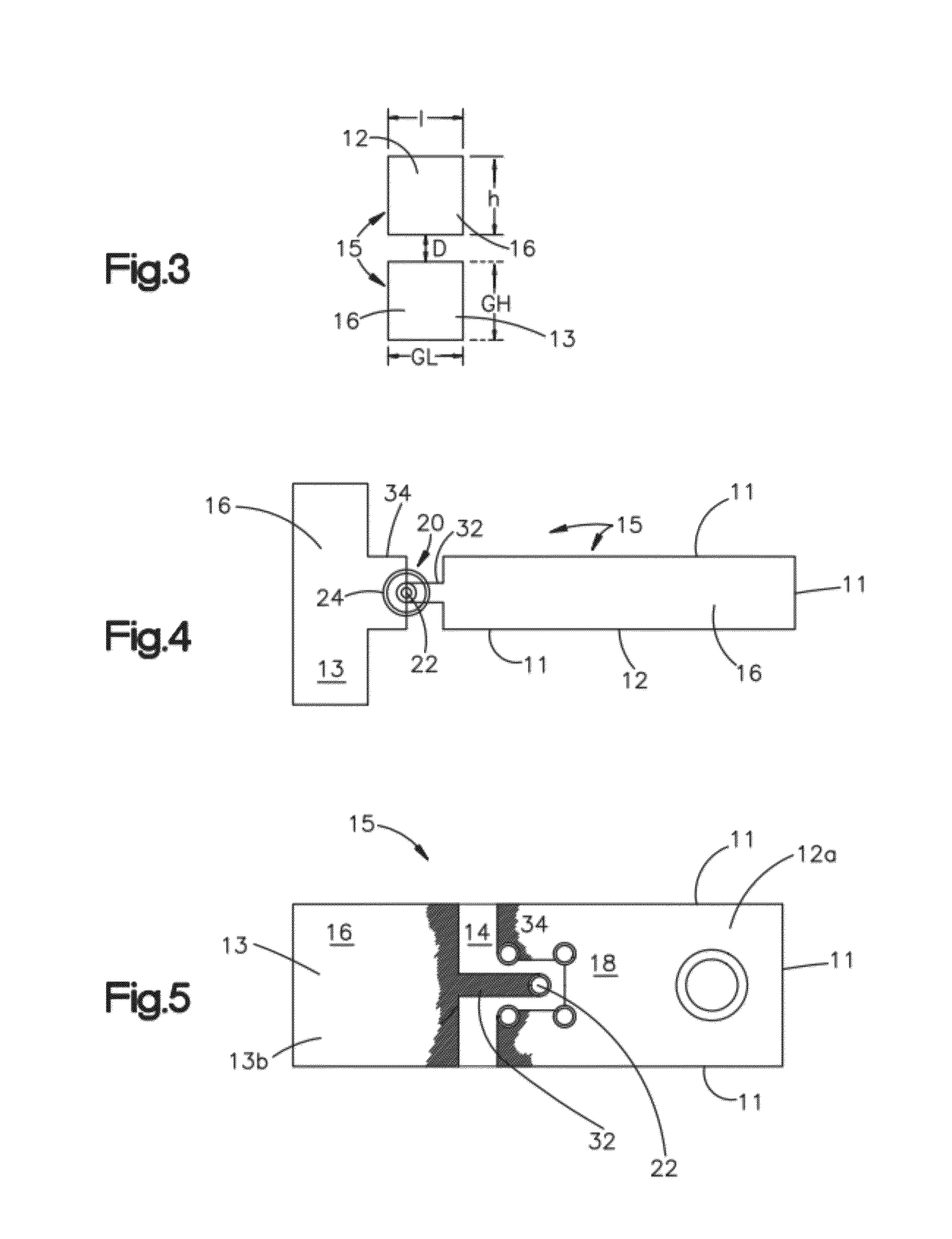
[0079]An Example of a practical application of the antenna system 9 of FIG. 2 for a wirelessly controlled robot 60 is shown in FIGS. 11 and 12. The wirelessly controlled robot 60 includes a circularly polarized antenna 65. The design of antenna 65 is schematically illustrated in FIG. 3 and shown generally in FIG. 5 wherein the radiating element 12 is approximately 25 mm in length l and about 20 mm in height h or width, while the antenna ground 13 is about 115 mm in length GL and about 55 mm in height GH or width, with the radiating element 12 being separated from the antenna ground 13 by about 5 mm (d about 5 mm). The radiating element 12 and antenna ground 13 are formed on the same circuit board or insulating substrate 14, where both the radiating element and antenna ground are relatively flat, thin, planar surfaces oriented in the same plane. In one embodiment, the antenna 65 is mounted about 12.5 mm behind the robot 60 (SP about 12.5 mm), and in this example behind the vertical p...

example 2

[0083]In another example, the same CP antenna 65 as used in the first example on the robot platform 60 was used on the same robot platform but the antenna 65 was mounted 25.4 mm (about 1 inch) behind the robot, e.g., behind the vertical plane of the robot and thus about 25.4 mm from the floating ground plane 90 or wire mesh 91. Again the antenna 65 preferably is mounted to the robot platform 60 so that it is isolated from and not electrically connected to the platform 60. The VSWR for the robot 60 with the CPA antenna 65 mounted 25.4 mm behind the robot (i.e., 25.4 mm from the floating ground plane) is shown in FIG. 15, while the antenna gain at 2.556 GHz is shown in FIG. 16. For the robot 60 with the CPA antenna 65 mounted 25.4 mm from the robot platform (the copper mesh), the VSWR is better than 2:1 from 1.6 GHz to 2.65 GHz as shown in FIG. 15. It should be noted that with the antenna mounted in the back of the robot 60, the gain is maximized behind the robot with the gain ranging...

example 3

[0084]In another example, an antenna 115 schematically illustrated as in FIG. 3, and similar in layout to FIG. 5, has a radiating element 12 having a length l of about 250 mm, and a height h or width of about 180 mm, separated a distance d of about 5 mm from antenna ground 13 is utilized. The antenna ground 13 has a length GL of about 990 mm and a height GH or width of about 990 mm. Both the radiating element 12 and antenna ground 13 are formed on a printed circuit board using printed circuit board technology. Thus, both the radiating element and the antenna ground are formed as thin metal foils or conductive coatings on an insulating substrate 14. Both the radiating element 12 and antenna ground 13 are relatively flat, thin, planar surfaces oriented in the same plane. Circularly polarized antenna 115 is mounted on a moveable vehicle 110 as shown in FIG. 17. The antenna 115 is mounted about an inch behind the vehicle 110. Preferably the antenna is mounted so that it is electrically ...


PUM


Abstract

A wireless device having an improved antenna system is disclosed comprising one or more antenna, preferably circularly polarized antenna, for transmitting or receiving a signal, and one or more floating ground planes, wherein the floating ground plane preferably is electrically isolated from and in sufficient proximity to the antenna so that it is inductively coupled to the antenna. The floating ground plane may comprise one or more of a strip, band, foil, plate, block, wire mesh, sheet or coating of conductive material and, for example, may be a relatively thin copper strip, band, foil or coating. The circularly polarized antenna, preferably comprises a flat planar shaped radiating element sized and configured to resonate at a predetermined, desired frequency, frequencies or band of frequencies, and a flat planar shaped antenna ground, both radiating element and antenna ground formed on the same printed circuit board. The radiating element is electrically isolated from the antenna ground but sufficiently close to resonate at the desired frequencies. Preferably the floating ground plane is larger than or more massive than the antenna ground, and preferably larger than or more massive than the radiating element. In a further embodiment the wireless device comprises a housing for interfacing with a user, the housing comprising a conductive contact exposed to the exterior of the housing and configured to be contacted by a user, wherein the conductive contact is electrically connected to the floating ground plane, preferably so that the user is coupled to the antenna and becomes part of the antenna system. The floating ground plane may also preferably be configured to substantially cover or overlap the antenna, and may also be configured to distribute and propagate the electromagnetic signals away from the head of the user.

Description

CROSS REFERENCE TO RELATED APPLICATIONS[0001]This application claims the benefit of U.S. Provisional Application No. 61 / 372,842 filed Aug. 11, 2010 and U.S. Provisional Application No. 61 / 381,611 filed Sep. 10, 2010, the entire contents of both of which are incorporated by reference herein.FIELD OF THE INVENTION[0002]The present invention relates to antennas that transmit and / or receive radio frequency (RF) signals and other electromagnetic signals including antennas for use in mobile, cellular or other wireless phones, desktop computers, notebook computers, laptop computers, tablets, servers, televisions, radios, Very High Frequency (VHF) radios, satellites, Ground Position Satellite (GPS) units, WiFi units, wireless routers, radio frequency controllers, robot devices, Bluetooth enabled devices, or other devices that communicate wirelessly.BACKGROUND OF THE PRESENT INVENTION[0003]Conventional antennas inclusive of television, radio, GPS, wireless routers, WiFi, wireless and cellula...

Claims


Application Information

Patent Timeline
Patent Type & Authority Applications(United States)
IPC IPC(8): H01Q1/48H01Q9/04H01Q1/24
CPCH01Q1/24H01Q1/38H01Q9/0428
Inventor CORNWELL, JAMES
Owner KAONETICS TECH
Why Eureka
Try Eureka