Silencer for reducing oil circulation rate of compressor

A compressor oil and muffler technology, which is applied in the direction of machines/engines, mechanical equipment, liquid fuel engines, etc., can solve problems such as reducing the oil circulation rate, and achieve the advantages of reducing the noise of dipole acoustic modal resonance and increasing production costs. Effect

Active Publication Date: 2010-11-10
SHANGHAI HITACHI ELECTRICAL APPLIANCES CO LTD
View PDF4 Cites 3 Cited by
  • Summary
  • Abstract
  • Description
  • Claims
  • Application Information

AI Technical Summary

Problems solved by technology

[0003] The research on reducing the oil circulat

Method used


Image

  • Silencer for reducing oil circulation rate of compressor
  • Silencer for reducing oil circulation rate of compressor
  • Silencer for reducing oil circulation rate of compressor

Examples


Embodiment 1

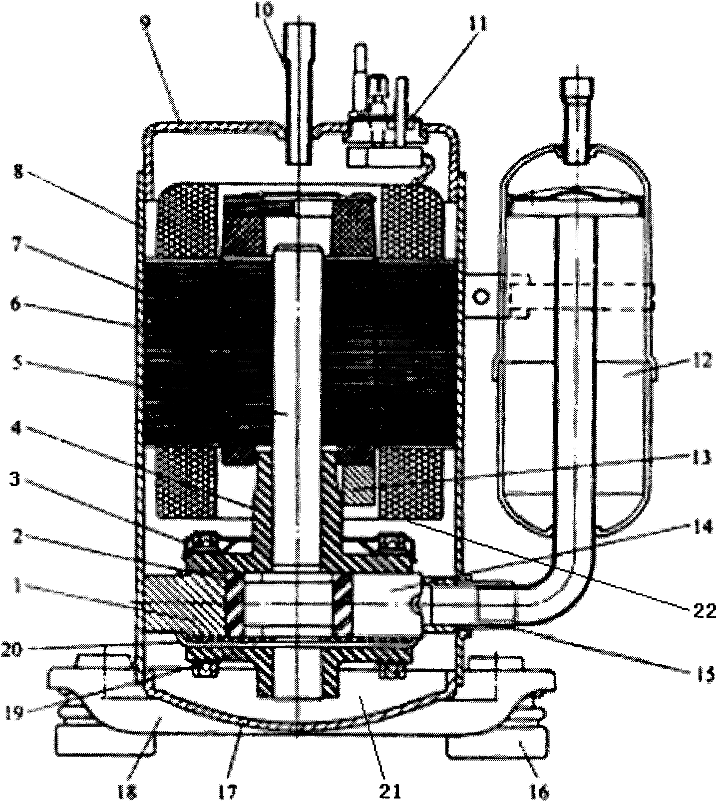
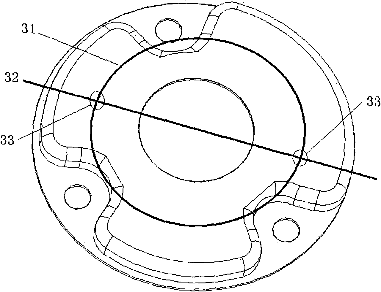
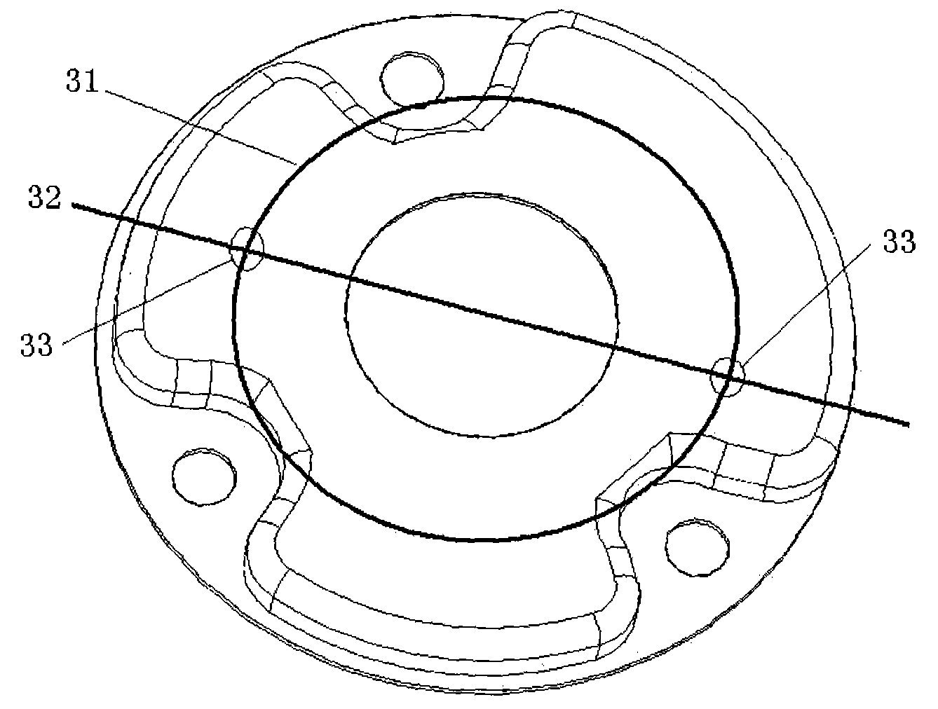
[0015] Such as Figure 1-2 As shown, a muffler that reduces the oil circulation rate of the compressor, the outlet position 33 of the muffler is arranged below the coil 22 of the motor stator 7, and the projection 31 of the coil center loop on the muffler is as follows figure 2 As shown, the refrigerant discharged from the muffler 3 is directly sprayed onto the coil 22. Due to the filtering (filter screen) function of the coil 22, the oil entrained in the refrigerant is difficult to continue to flow upward with the refrigerant, so it can fall back to the oil pool 21, so The amount of oil discharged from the compressor by the refrigerant is significantly reduced, resulting in a lower oil circulation rate.

[0016] Under the premise of ensuring that the outlet of the muffler 3 is aligned with the coil 22, the outlet of the muffler 3 is also located on the dipole acoustic mode node line 32 of the cavity in the lower part of the compressor housing, which can prevent the mode from...


PUM


Abstract

The invention relates to a silencer for reducing the oil circulation rate of a compressor. An outlet of the silencer is arranged under a motor stator coil, a cold medium discharged from the silencer is directly sprayed on the coil, and oil carrying in the cold medium falls back into an oil tank through the filtration by the coil, so the oil circulation rate is decreased. Compared with the prior art, the invention has the advantages of capability of reducing the oil circulation rate and noise of the compressor and the like.

Description

technical field [0001] The invention relates to a rotary air conditioner compressor, in particular to a muffler for reducing the oil circulation rate of the compressor. Background technique [0002] When the refrigerating machine oil of the compressor is discharged from the compressor with the refrigerant and circulates in the refrigerating system, part of the refrigerating machine oil will accumulate in the pipeline of the air conditioning system, which will cause problems such as difficult backflow, reduced heat transfer efficiency, and compressor failure. How to reduce the oil circulation rate is of great significance to the performance and reliability of the compressor. The problem of reducing the oil circulation rate is somewhat difficult because it involves a wide range of mechanisms. [0003] The research on reducing the oil circulation rate by improving the muffler is still blank. Contents of the invention [0004] The object of the present invention is to provid...

Claims


Application Information

Patent Timeline
IPC IPC(8): F04C29/06
Inventor 周易李双
Owner SHANGHAI HITACHI ELECTRICAL APPLIANCES CO LTD
Why Eureka
Try Eureka