
Devices and methods for offset and similar printing systems
a technology of printing system and printing device, applied in the direction of instruments, electric digital data processing, electrical apparatus, etc., can solve problems such as far from ideal
- Summary
- Abstract
- Description
- Claims
- Application Information
AI Technical Summary
Problems solved by technology
Method used
Image

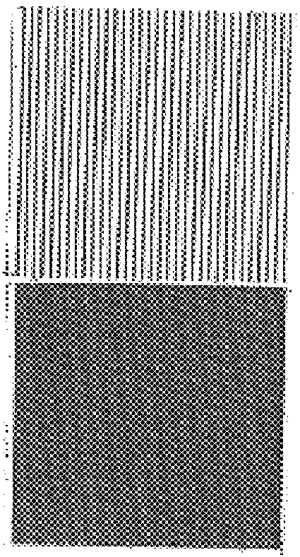
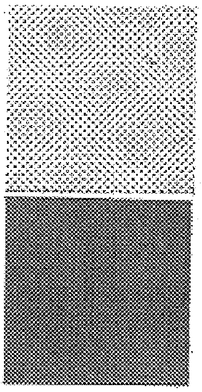

Examples
example 2 fig.3 (
EXAMPLE 2 FIG. 3 (girl)
An image was exposed through a 55 line / in screen (Beta Screens) onto a standard lith film (Agfa 812) and processed in standard lith developer (Agfa G 9OP). This was reduced about 55%, on Agfa 812 film and developed in Agfa G 9OP generating a ruling of 100 lines / in. This resultant "line screened" image was exposed onto a standard lith (Agfa 812) and developed in standard lith developer (Agfa G 9OP). The resulting black and white contact positive using Agfa-Gevaert Litex paper developed in D-11 is shown in FIG. 3a. As a Control, the same continuous tone image used above was exposed through a conventional dot screen (Agfa Gevaert) with a ruling of 100 dots / in, onto a standard lith film (Agfa 812) and developed in a standard lith developer (Agfa G 9OP). The resulting contact positive on Agfa-Gevaert Litex paper developed in D-11 is shown in FIG. 3b. This demonstrates that the "line screen" image produces a smoother transition of tones (i.e. a better continuous ton...
example 3 fig.4 (
EXAMPLE 3 FIG. 4 (Beach Scene)
An Itek continuous tone scanner (Model 200) outputs at 500 lines / in . FIG. 4 shows the results of this 500 line / in output onto a standard scanner film (Agfa 812) using a special lith developer, containing a hydroquinone developing agent in combination with carbonate, bicarbonate and halide salt together with sodium formaldehyde sulfoxylate and formaldehyde as described in U.S. Pat. No. 4,598,040, the teachings of which are incorporated herein by reference. (At this resolution, a color separation can be made without requiring adjustment of angles, to minimize Moire).
Careful inspection of FIG. 4 reveals in the highlight area, relatively, continuous linesy comprising short line segments in excess of 5.mu. spaced close enough to each other to give an impression of continuity along their axis, and in the shadows, longer line segments which tend to "close up" partially, near Dmax. As will be realized from this Figure, in the highlight region the width of the ...
example 4 (fig.5)
EXAMPLE 4 (FIG. 5)
A colour separation set (cyan, magenta, yellow, black) was prepared, where each colour was produced electronically as a line screen, each aligned 30 degrees from each other, onto a standard red sensitive scanner film (Anitec) and developed in standard rapid access developer (Anitec). at a ruling of 254 lines / in using a LaserPaint(R)Macintosh (R) / Linotronic 300(R) System, Contacts of each of the 4 films in the set were made using standard lith film (Agfa) 812) and developing in a special lith developer, as described in U.S. Pat. No. 4,598,040. The resulting colour print is shown in FIG. 5a. The control was made using a normal 2-directional electronically generated screen format with a ruling of 254 dots / in the screen, angles being dealt with in the standard way. The resulting colour print is shown in FIG. 5b. Note, that in this case, this colour separation generates 8 lines effectively (2 for each colour) whose relative angles have been considered to minimize Moire ...
PUM
| Property | Measurement | Unit |
|---|---|---|
| transparent | aaaaa | aaaaa |
| transparent | aaaaa | aaaaa |
| color | aaaaa | aaaaa |
Abstract
Description
Claims
Application Information