Method and apparatus for compensation for time varying nozzle misalignment in a drop on demand printhead

a technology of print head and nozzle, applied in the field of drop on demand printhead, can solve the problems of substantial reduction in yield, inability to make large monolithic print head from contiguous substrate segments such as silicon, and the spacing between adjacent print head segments must be extremely accurately controlled. achieve the effect of convenient and effective manner

Inactive Publication Date: 2007-04-10
SILVERBROOK RES PTY LTD +1
View PDF12 Cites 19 Cited by
  • Summary
  • Abstract
  • Description
  • Claims
  • Application Information

AI Technical Summary

Benefits of technology

[0011]It is an object of the present invention to provide for a mechanism for compensating for relative displacement of overlapping print head segments during operation in an effective and convenient manner.

Problems solved by technology

Unfortunately, it is impractical to make large monolithic print heads from a contiguous segment of substrate such as a silicon wafer substrate.
This is primarily a result of the substantial reduction in yield with increasing size of construction.
The problem of yield is a well studied problem in the semi-conductor industry and the manufacture of ink jet devices often utilizes semi-conductor or analogous semi-conductor processing techniques.
Unfortunately, the extremely high pitch of ink ejection nozzles required for a print head device means that the spacing between adjacent print head segments must be extremely accurately controlled even in the presence of thermal cycling under normal operational conditions.
Ambient conditions and the operational environment of a print head may result in thermal cycling of the print head in the overlap region resulting in expansion and contraction of the overlap between adjacent print head segments which may in turn lead to the production of artifacts in the resultant output image.
Artifacts are produced due to the limited resolution of the print head to represent a continuous tone image in a binary form and the ability of the human eye to detect 0.5% differences in colour of adjacent dots in an image.

Method used


Image

  • Method and apparatus for compensation for time varying nozzle misalignment in a drop on demand printhead
  • Method and apparatus for compensation for time varying nozzle misalignment in a drop on demand printhead
  • Method and apparatus for compensation for time varying nozzle misalignment in a drop on demand printhead

Examples


Embodiment Construction

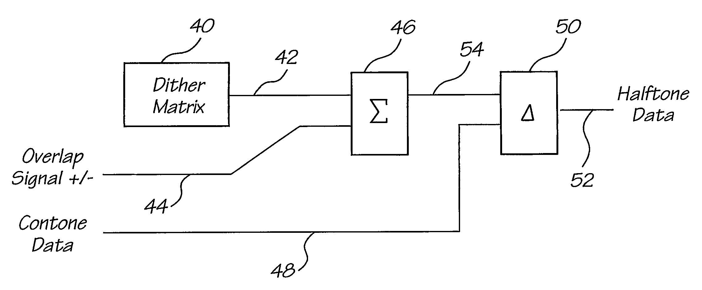
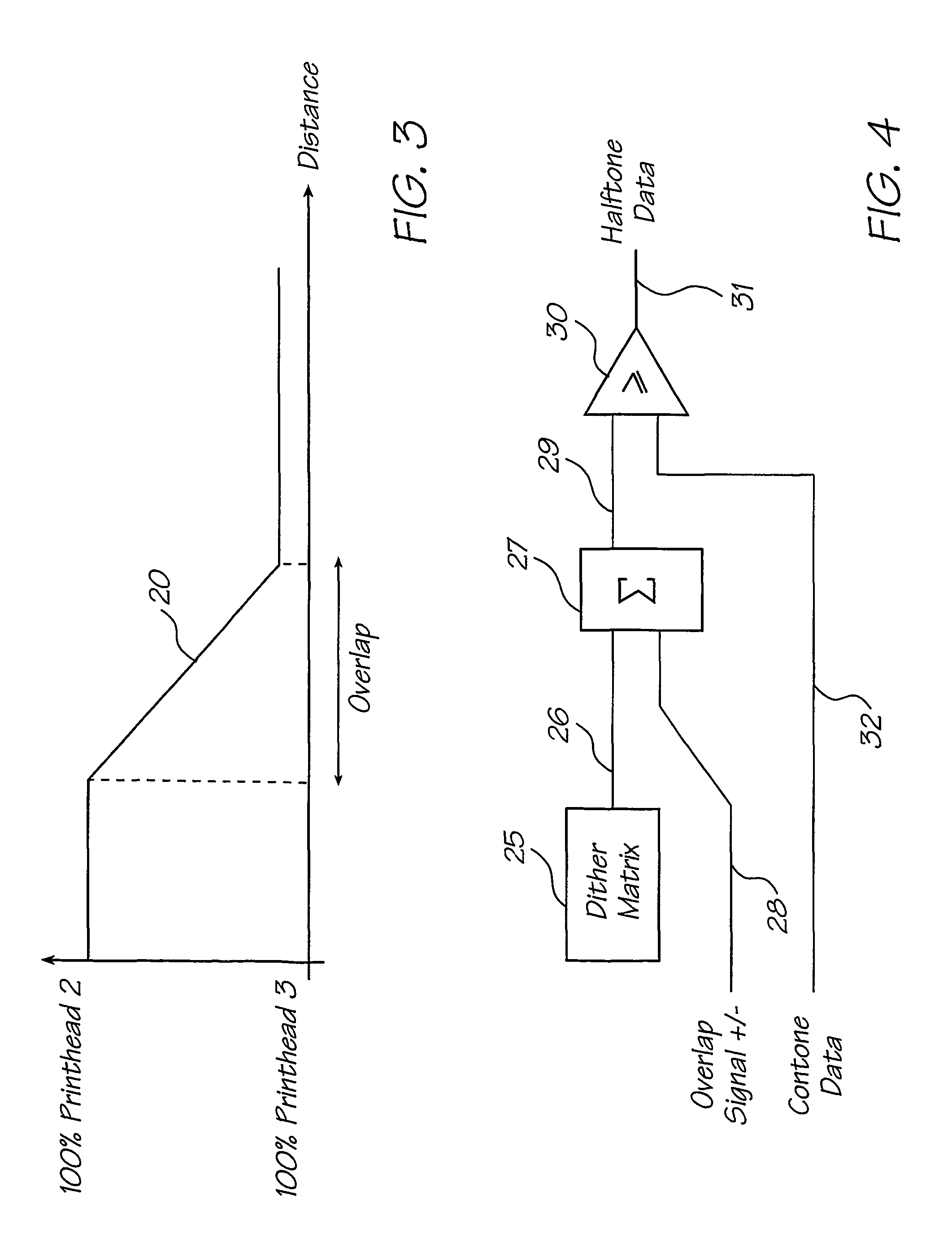
[0023]In a first embodiment, a method of compensation for the temperature varying relative displacement of adjacent print head segments is provided by the utilization of a digital processing mechanism which adjusts for the overlap between adjacent segments.

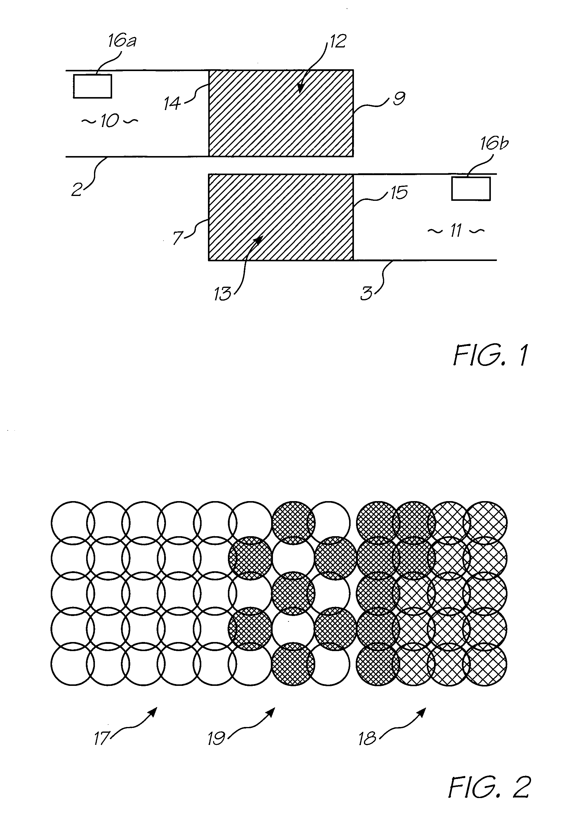
[0024]In a print head covering an A4 page width there may be 10 segments having 9 overlapping portions arranged in a repeating sequence of staggered pairs. Initial alignment of segments can be made within 10 microns using techniques well known in the art of monolithic fabrication techniques. The width of a segment for a 6 colour ink arrangement would be approximately 225 microns assuming the nozzles of a segment are arranged on 16 micron centres in a zig-zag pattern longitudinally.

[0025]In this embodiment, a temperature sensor 16a, 16b is placed on each print head segment so as to provide for a measure of the current temperature characteristics of each print head segment. The current temperature measurement can then be utilized to...


PUM


Abstract

A method and apparatus is provided for compensating for variable overlap between segments of a page width print head system to reduce visually perceptible artifacts due to misalignment of adjacent overlapped segments. One method employs a summator which sums a current dither value from a dither matrix with an overlap signal to provide an output value which is then compared in a comparator with an input continuous tone data value providing an output compensated dither value to control nozzles in the overlap region of the segments. Another method uses a software program to provide the compensated dither matrix. A sensor provides a measure of the degree of overlap of the segments to generate the overlap signal. The sensor may sense temperature or relative displacement of the segments. The degree of overlap may be determined for various temperatures and stored in a ROM.

Description

CROSS REFERENCE TO RELATED APPLICATIONS[0001]This is a 371 of PCT / AU00.00593 filed on May 24, 2000, all of which are herein incorporated by reference.FIELD OF THE INVENTION[0002]The present invention relates to the field of ink jet printing and in particular discloses a method and apparatus for the compensation for the time varying nozzle misalignment of a print head assembly having overlapping segments.CO-PENDING APPLICATIONS[0003]Various methods, systems and apparatus relating to the present invention are disclosed in the following co-pending applications filed by the applicant or assignee of the present invention simultaneously with the present application:[0004]10 / 29643410 / 29643570639936874868689635810 / 296534697420470559306893109682424210 / 29652410 / 29652270700986805419[0005]The disclosures of these co-pending applications are incorporated herein by cross-reference.BACKGROUND OF THE INVENTION[0006]In the applicant's co-pending application PCT / AU98 / 00550, a series of ink jet printi...

Claims


Application Information

Patent Timeline
Patent Type & Authority Patents(United States)
IPC IPC(8): B41J29/38B41J29/393B41J2/01B41JB41J2/05B41J2/145B41J2/155B41J2/205B41J2/21B41J2/505
CPCB41J2/04505B41J2/04563B41J2/04586B41J2/0459B41J2/155B41J2/2135B41J29/393H04N1/50
Inventor SILVERBROOK, KIALAPSTUN, PAUL
Owner SILVERBROOK RES PTY LTD
Why Eureka
Try Eureka