Tactile feedback interface device including display screen

a display screen and tactile feedback technology, applied in the field of control devices, can solve the problems of inconvenient use of the standard joystick device in controlling functions, device clumsy and ineffective, and may not include all the features of the prior art, and achieve the effect of convenient and effective use, convenient and effective manner, and added functionality and efficiency

Inactive Publication Date: 2006-12-19
IMMERSION CORPORATION
View PDF67 Cites 86 Cited by
  • Summary
  • Abstract
  • Description
  • Claims
  • Application Information

AI Technical Summary

Benefits of technology

[0006]The present invention provides a control device that allows a user to interface with an apparatus in a convenient and effective manner. The control device can also be provided with force feedback for added functionality and efficiency.
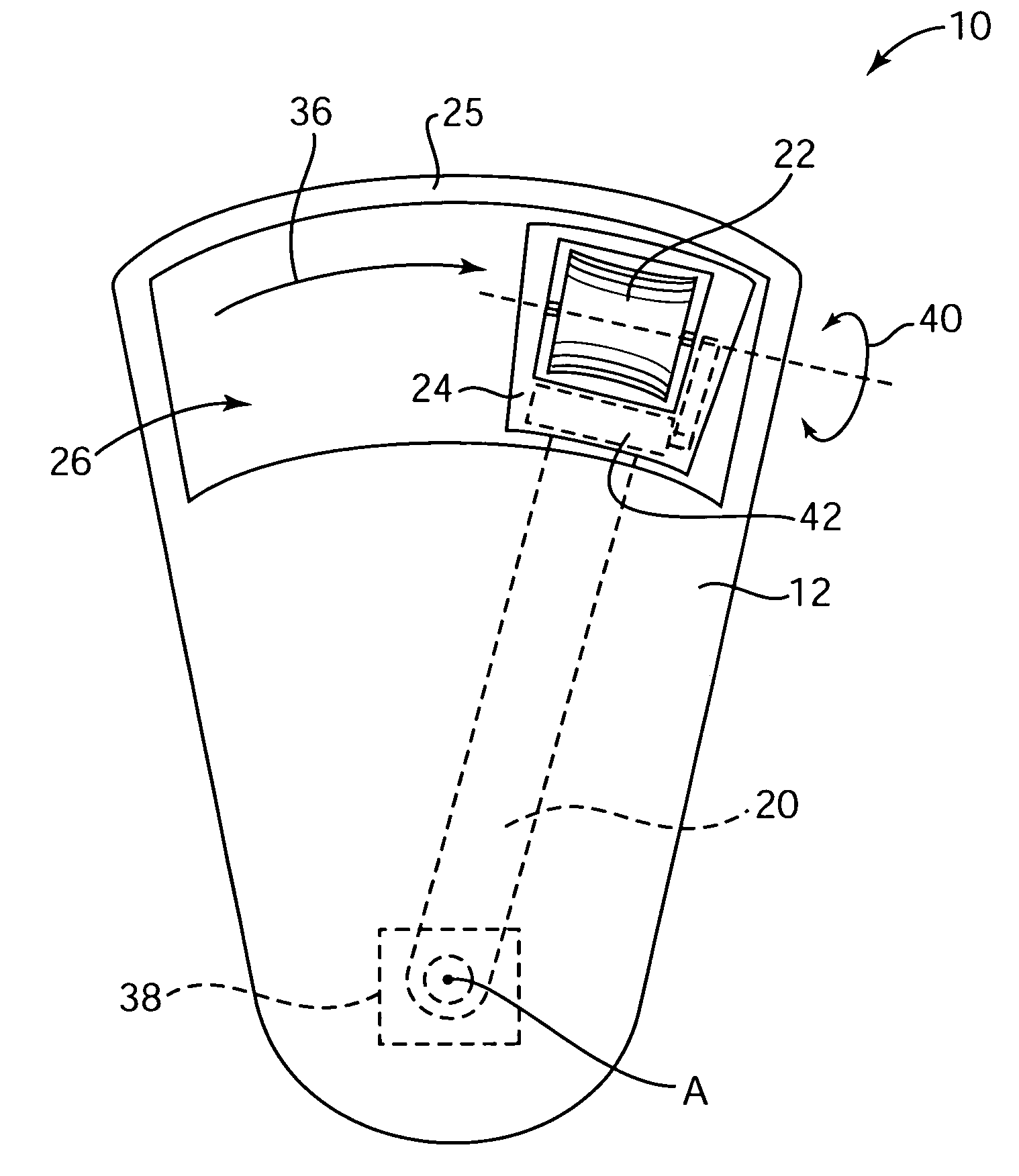
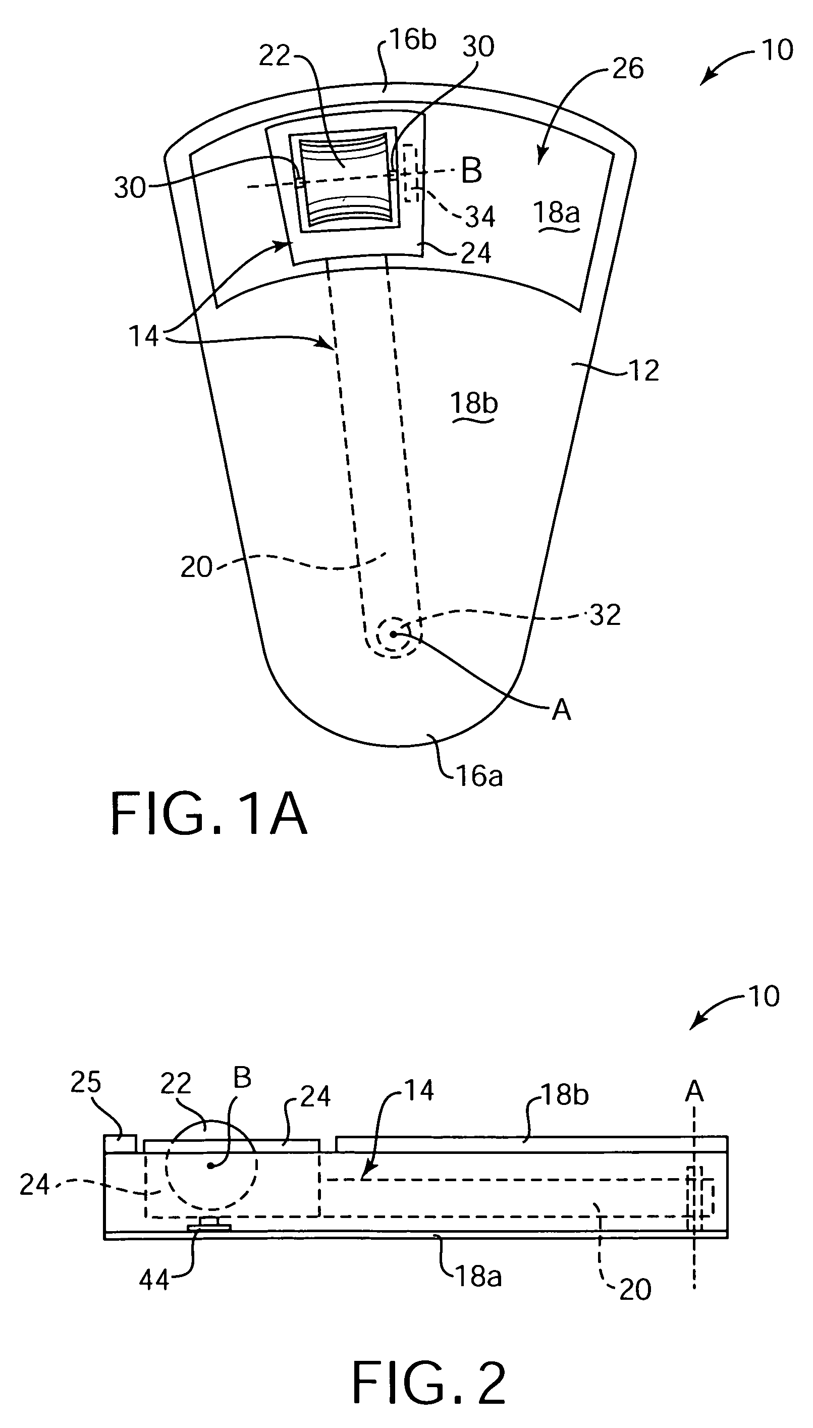
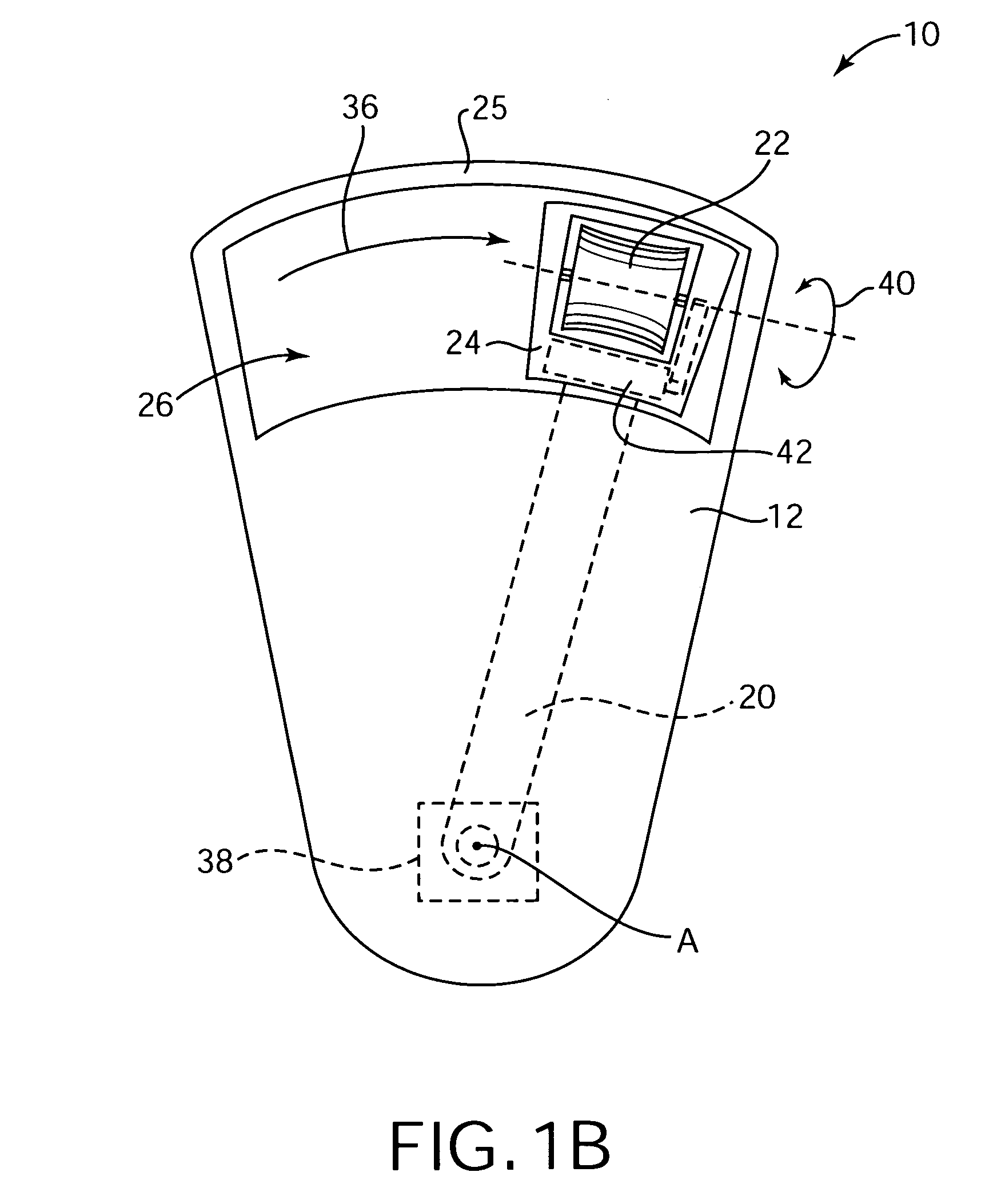
[0010]The device and method of the present invention provide an interface to an apparatus that provides greater control functionality and convenience for the user. The arcuate or linearly moving carrier portion is easily moved by a user's thumb, providing horizontal control over a cursor or other input. The rotatable wheel provided in the carrier allows the same finger of the user to control vertical motion of a cursor or control a different function of an apparatus. However, since the wheel rotates in a single position, the length of the carrier arm need not be adjusted greatly for differently-sized hands. Force feedback may also be added to the control device to provide the user with greater control and to inform the user of options and selections through the sense of touch.

Problems solved by technology

Typical control devices of the prior art, however, may not include all these features.
For example, a standard joystick device may not be very convenient for use in controlling functions since it either requires two hands to operated (one hand holding the device, the other hand operating the joystick), or it requires a table top or other surface on which to rest the joystick.
Some attempts have been made to develop one-handed joysticks, but these devices often end up clumsy and ineffective.
Similarly, gamepad controllers, commonly used to interface with video games provided by game consoles, require the use of two hands and are thus inconvenient in many applications.

Method used


Image

  • Tactile feedback interface device including display screen
  • Tactile feedback interface device including display screen
  • Tactile feedback interface device including display screen

Examples


embodiment 110

[0058]FIG. 10 is a top plan view of a different embodiment 110 of control device 10 in which a ball or sphere 112 is included at the back portion of the control device 110 to provide mouse-like functionality. Ball 112 can be held in place by multiple rollers, similar to standard mouse input devices, where two of the rollers are coupled to sensors to provide input signals for the horizontal movement and vertical movement, respectively, of the control device 110 on a surface. In a different embodiment, control device 110 can be provided with a wheel, similar to device 100, to input control signals for only one degree of freedom of movement (forward-back motion or left-right motion).

embodiment 120

[0059]FIG. 11 is a top plan view of a different embodiment 120 of the control device 10 of the present invention, in which ball bearings are provided to allow the carrier portion 24 to move left and right in the opening 26 of the housing 12. Housing 12 preferably includes tracks 122 in the edges of opening 26, in which are seated ball bearings 124 which are rotatably coupled to the carrier portion 24. The ball bearings roll within the tracks as the carrier portion 24 is moved left or right within the opening 26, such that minimal friction is provided and smooth movement obtained. Thus, in such an embodiment, the arm member 20 is not required to permit movement of the carrier portion 24. In other embodiments, sliding bearing surfaces can be used; however, such bearings tend to introduce greater friction in the movement of the portion 24. The opening 26 and tracks 22 may be curved as shown in FIG. 11, or alternatively may be straight. A roller 22 or any other combination of rollers or...

embodiment 130

[0060]FIG. 12 is a top plan view of a different embodiment 130 of the control device of the present invention, in which a local display screen 132 is coupled to the housing of the control device. Screen 132 can display information either stored in memory local to the control device 10, or information received from an apparatus interfaced with the control device 130, such as a host computer or other device. For example, graphical and textual information can be displayed to assist the user in determining functions of the control device as related to the current program running on the host computer. In one example, as the user controls a displayed cursor over menu selections, information related to the menu selections from the host computer is displayed on the local display 132. In other embodiments, a larger display screen can be included to provide a self-contained, portable computer or game device, having graphical and textual images displayed thereon. The display screen 132 can be ...


PUM


Abstract

A control device including a housing and a carrier moveable with respect to the housing in a first rotary degree of freedom. A first sensor senses the movement of the carrier and outputs a first control signal. A roller rotatably coupled to the carrier rotates with the carrier in the first degree of freedom and rotates independently of the carrier in a second rotary degree of freedom. A second sensor senses rotary motion of the roller and outputs a second control signal. Preferably, an arm member coupled between carrier and housing pivots about an axis. A third sensor, such as a switch, can be used to detect when the carrier has been pushed in a direction substantially orthogonal to a plane of rotation of the arm member. Force feedback can also be provided in the rotary degrees of freedom of the control device.

Description

CROSS REFERENCE TO RELATED APPLICATIONS[0001]This application is a continuation of U.S. application Ser. No. 09 / 203,908, filed Dec. 1, 1998 now U.S. Pat. No. 6,256, 011, which claims priority to provisional applications No. 60 / 067,382, filed Dec. 3, 1997 by Craig F. Culver, entitled “An Improved Multi-Function Control with Feedback,” and No. 60 / 067,381, filed Dec. 3, 1997 by Craig F. Culver, entitled “Interactive Panels for Instrument Control,” all of which are incorporated herein by reference.BACKGROUND OF THE INVENTION[0002]This invention relates generally to control devices, and more particularly to force feedback control devices.[0003]Control devices can be used for a variety of different control tasks. A user can conveniently select or operate different functions and features of a device using the control device. In some cases, the control device allows a user to operate or interface with a device remotely, without having to operate controls located on the housing of the device...

Claims


Application Information

Patent Timeline
Patent Type & Authority Patents(United States)
IPC IPC(8): G09G5/08G06F3/00G06F3/01G06F3/033
CPCG06F3/016G06F3/0338G06F3/03543G06F3/0362G06F2203/014
Inventor CULVER, CRAIG F.
Owner IMMERSION CORPORATION
Why Eureka
Try Eureka