Energy absorbing system and method

a technology of energy absorption system and energy absorption, which is applied in the direction of roadway safety arrangements, roads, construction, etc., can solve the problems of increasing the number of race car drivers who have been seriously injured or killed, and the installation and maintenance is difficult, and achieves the effect of convenient installation

Inactive Publication Date: 2003-04-29
MOORE JOSEPH W
View PDF20 Cites 16 Cited by
  • Summary
  • Abstract
  • Description
  • Claims
  • Application Information

AI Technical Summary

Benefits of technology

Thus, with the known problems and disadvantages of present crash safety methods and devices, the present invention was conceived and one of its objectives is to provide an energy absorbing system for attachment to a rigid racetrack wall or other support to more safely dissipate the energy generated during vehicle crashes for driver protection.
It is still another objective of the present invention to provide an energy absorbing system which can be easily installed on existing racetrack and other rigid walls or supports.
It is yet another objective of the present invention to provide an energy absorbing system which utilizes collapsible cushions formed with a tough, durable outer skin or casing and a less dense inner filler.
It is still a further objective of the present invention to provide a method of safely dissipating energy such as caused by a vehicle striking a wall utilizing the energy absorbing system described herein.

Problems solved by technology

While such measures have provided protection for spectators, increasing numbers of race car drivers have been seriously injured or killed as their vehicles impact the rigid walls even with various types of standard crash barriers being utilized.
While all of these prior devices are beneficial in certain circumstances, most are difficult to install and maintain and a satisfactory system for preventing serious injury to race car drivers traveling at high speeds is still needed which is practical, safe and easily maintainable.

Method used


Image

  • Energy absorbing system and method
  • Energy absorbing system and method
  • Energy absorbing system and method

Examples


Embodiment Construction

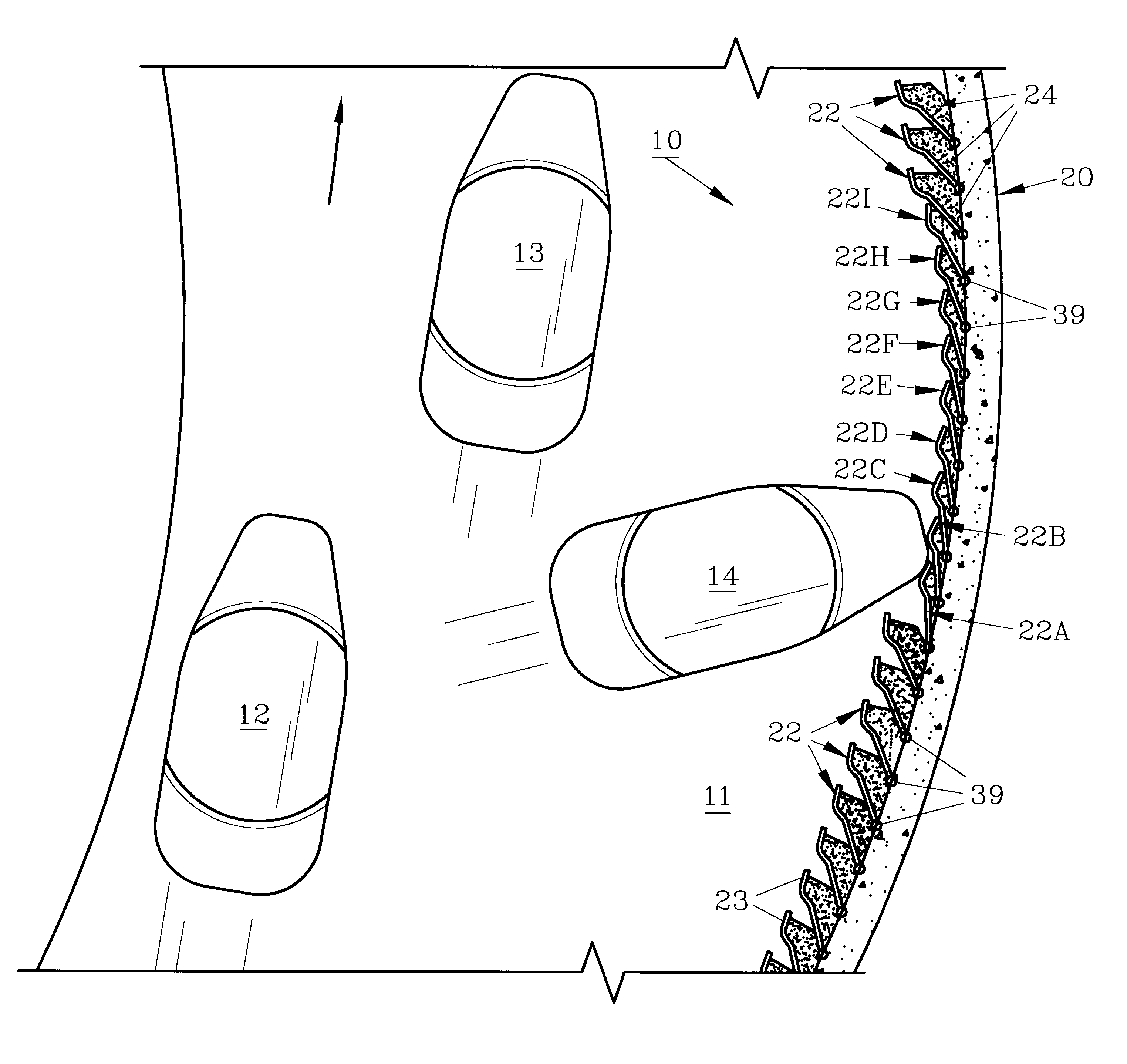
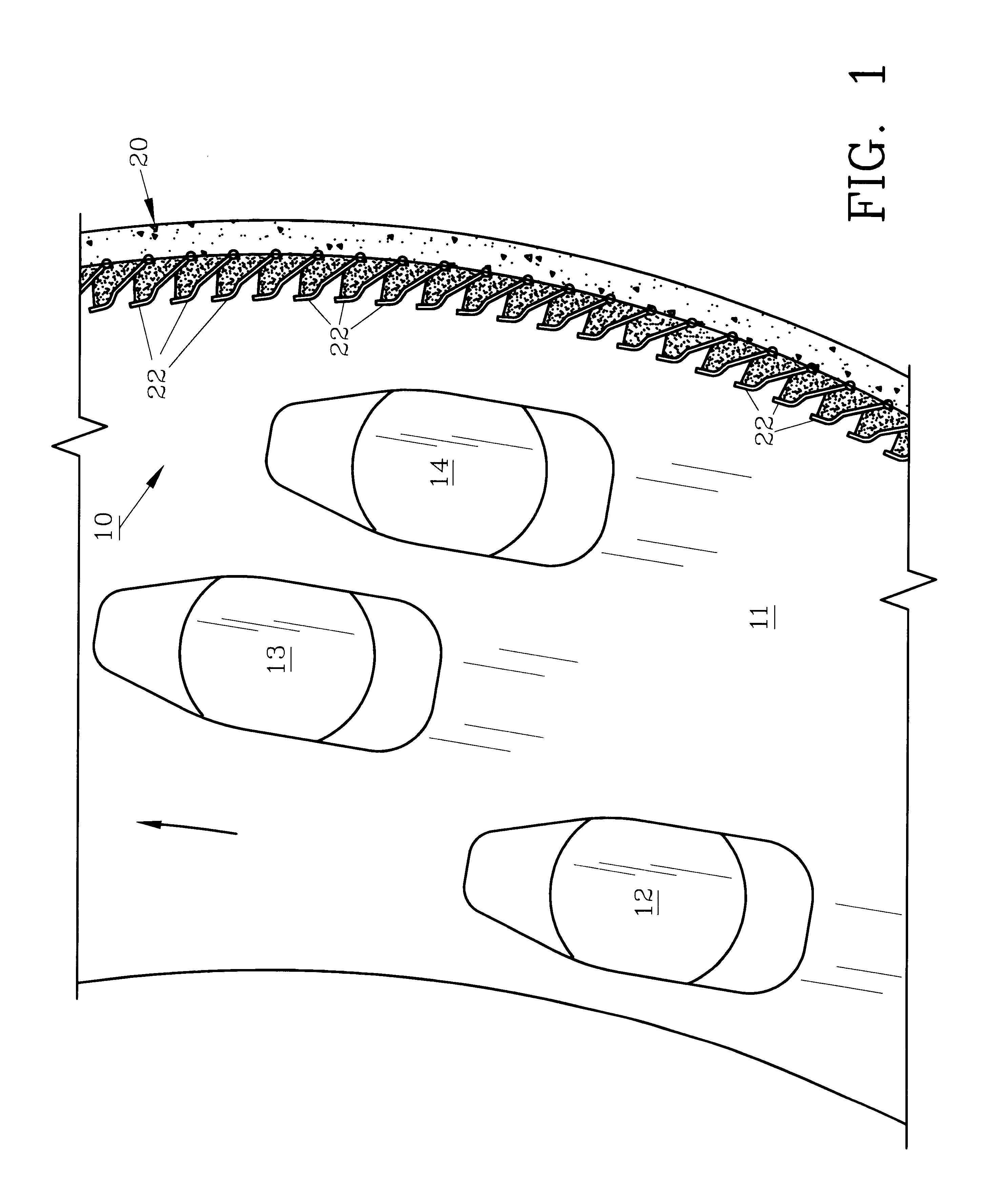
For a better understanding of the invention and its method of operation, turning now to the drawings, FIG. 1 shows preferred energy absorbing system 10 in conjunction with racetrack 11 having race cars 12-14 thereon. Energy absorbing system 10 is joined to the inside of concrete wall 20 which surrounds the outer perimeter of racetrack 11. Energy absorbing system 10 includes a plurality of preferred energy absorbing units 22 which are each pivotally mounted to wall 20 at an angle (.o slashed.) of preferably about 30.degree. (FIG. 6) from the normal direction of race car travel. As would be understood, energy absorbing system 10 is preferably placed completely around racetrack 11 but can be only proximate the turns as desired.

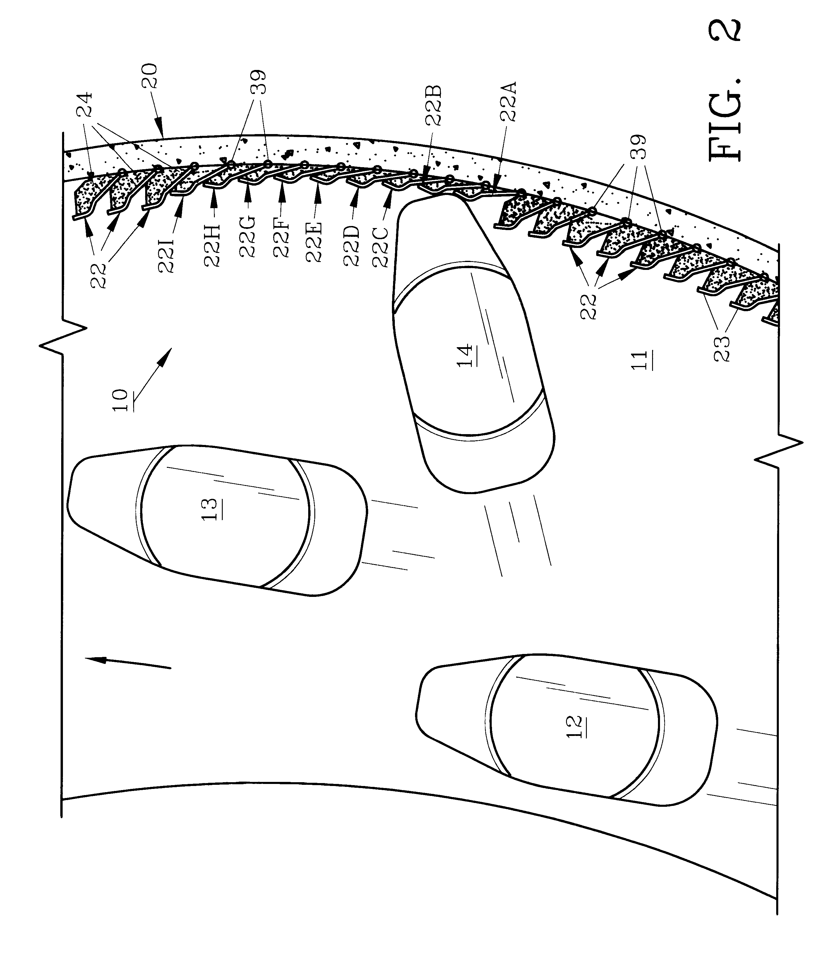
In FIG. 2, race car 14 has veered from its normal race direction (as shown by the accompanying arrow) and has struck energy absorbing system 10 by impacting energy absorbing units 22A and 22B. By striking energy absorbing units 22A and 225, said energy absorbing ...


PUM


Abstract

An energy absorbing system is provided to protect vehicle drivers and the like from serious injury which may occur when the vehicle strikes a wall or other rigid structure. The system utilizes a plurality of energy absorbing units having hinged plates with a cushion backing which dampens the impact by swinging in an overlapping fashion. The plates are formed from steel and the cushion is formed with a high density outer polymeric casing and a relatively low density filler within.

Description

The invention herein pertains to an energy absorbing system used as a vehicle crash barrier, lane barricade or lane divider and particularly pertains to an energy absorbing system for attachment to a rigid racetrack wall.DESCRIPTION OF THE PRIOR ART AND OBJECTIVES OF THE INVENTIONIn recent years all forms of vehicle racing have become increasing popular and speeds have increased in many events to over 200 miles per hour (321.8 k / h). To protect the large audiences which now attend the races, track owners have installed rigid perimeter walls, barriers and the like, usually formed of concrete reinforced with steel. While such measures have provided protection for spectators, increasing numbers of race car drivers have been seriously injured or killed as their vehicles impact the rigid walls even with various types of standard crash barriers being utilized. Conventional crash barriers include stacks of vehicle tires, compression guardrails; plastic, liquid or sand filled barrels or the ...

Claims


Application Information

Patent Timeline
Patent Type & Authority Patents(United States)
IPC IPC(8): E01F15/00E01F15/14
CPCE01F15/145
Inventor MOORE, JOSEPH W.
Owner MOORE JOSEPH W
Why Eureka
Try Eureka