Dynamic High Energy Switch

Active Publication Date: 2014-07-31
POWERMETRICS INT
View PDF4 Cites 2 Cited by
  • Summary
  • Abstract
  • Description
  • Claims
  • Application Information

AI Technical Summary

Benefits of technology

The present invention is a new switching circuit that can safely transfer energy from an electrical power source to a load without causing any harm. This circuit solves the problems of conventional circuit protection devices and power switching devices.

Problems solved by technology

Traditionally electronic switches have been unable to switch high-energy loads effectively resulting in damage to the switch, the capacitor, and the devices to which power is being provided.
Effective resolution of this problem has been too costly and, without a switch that could effectively switch high-energy capacitors in and out of a circuit, the state of the art has been unable to provide suitable avenues of controlling the power imbalance issues and other related problems.
Consequently, it was impossible not to cause damage to switches, capacitors and even motors simply because there was no way to effectively switch capacitance in and out of high power circuits in such a way to efficiently resolve imbalance and harmonics issues.
In addition, there is no practical way that a capacitor can be discharged rapidly so that it can to switched on and rapidly charged, or that guarantees that the capacitor is kept in its discharge state in the event of a power loss.
As we have experienced there have been many efforts to increase efficiency, reduce power consumption, and mitigate power delivery costs but these efforts have not effectively addressed the growing problem described above.

Method used


Image

  • Dynamic High Energy Switch
  • Dynamic High Energy Switch

Examples


Embodiment Construction

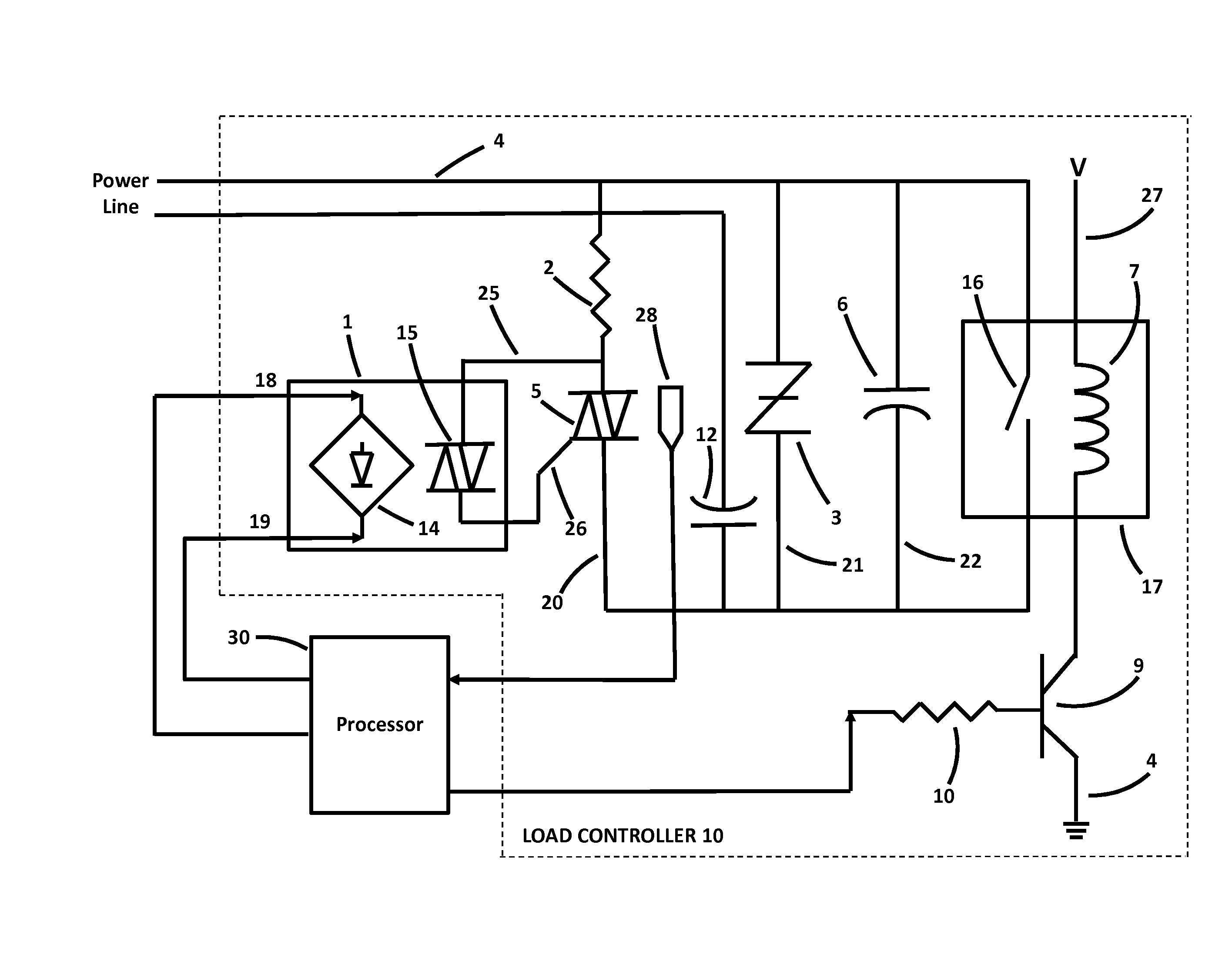
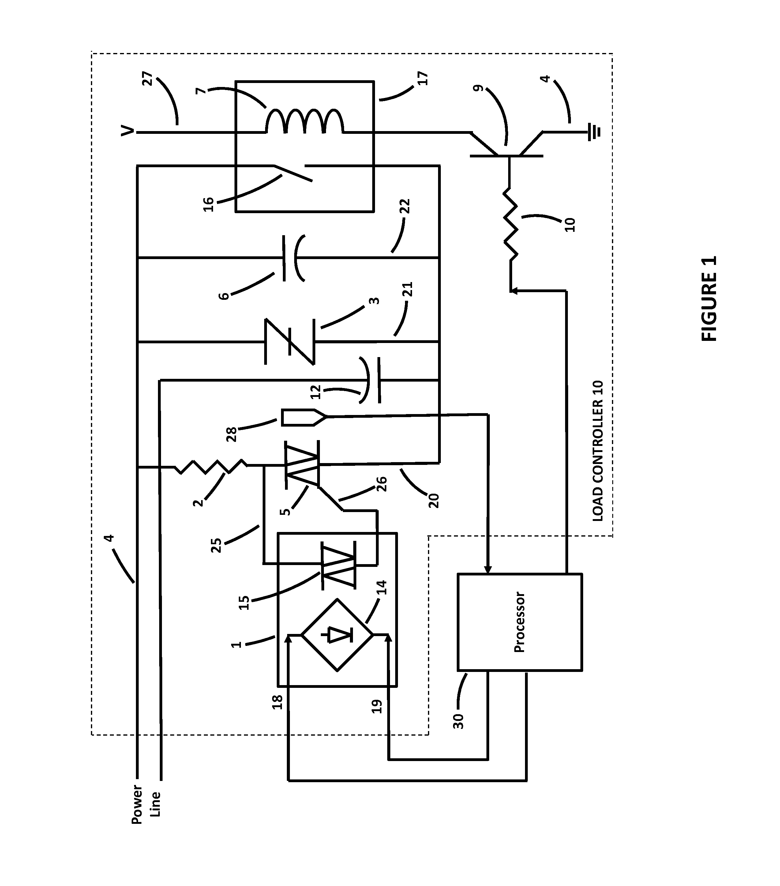
[0012]The present invention provides a novel capacitor switching system that can safely transfer energy from a source to a load while overcoming the deficiencies of conventional circuit protection devices and switching devices.

[0013]In FIG. 1 current travels in line 4 and through resistor 2, which limits the current that can flow through opto coupler 1 via lead 25. A control circuit connected to leads 18 and 19 is isolated from other circuitry by the operation of opto coupler 1. The opto coupler operates as a load sensing device that contains diode 14 and a triac 15 that senses operating conditions and establish the zero crossing of the wave-form of the AC current on line 4. When opto coupler 1 is activated by its control circuit triac 15 in opto coupler 1 conducts a flow of current to line 26. Triac 15 allows some of the current passing through resistor 2 to pass onto the gate terminal of triac 5 via line 26. Triac 15 operates as a load comtroller that provides a signal to diode 14...


PUM


Abstract

A dynamic high-energy switch used for correcting load imbalance through connecting and disconnecting capacitance in a power feed circuit.

Description

[0001]This application claims priority to U.S. Ser. No. ______ entitled “Dynamic High Energy Power Line Capacitor Switching System”, filed on Feb. 11, 2012, naming Hamid Pishdadian of Warwick, R.I. as inventor, the contents of which are herein incorporated by reference in their entirety.FIELD OF INVENTION[0002]This invention relates to switching circuits. More specifically, effectively switching on and off a capacitor or capacitor bank within a closed system. This invention is applicable to various applications such as arc welding, magnetizing materials, and switching capacitors.BACKGROUND OF THE INVENTION[0003]Traditionally electronic switches have been unable to switch high-energy loads effectively resulting in damage to the switch, the capacitor, and the devices to which power is being provided. Effective resolution of this problem has been too costly and, without a switch that could effectively switch high-energy capacitors in and out of a circuit, the state of the art has been ...

Claims


Application Information

Patent Timeline
IPC IPC(8): G05F1/70
CPCG05F1/70H02J3/1864H03K17/725H03K17/79Y02E40/10H02J3/1821
Inventor PISHDADIAN, HAMID
Owner POWERMETRICS INT
Why Eureka
Try Eureka