Combined illuminated reticle and focus knob

a technology of illuminated reticles and focus knobs, which is applied in the field of riflescopes, can solve problems such as affecting the accuracy of scopes and being susceptible to impacts

Inactive Publication Date: 2004-04-13
LIGHTFORCE USA
View PDF5 Cites 72 Cited by
  • Summary
  • Abstract
  • Description
  • Claims
  • Application Information

AI Technical Summary

Problems solved by technology

One drawback with side mounted reticle control knobs is that they provide a port for water or moisture to enter the erector tube, the eyepiece, or the scope body.
Another drawback is the control knob or eyepiece must be relatively large in order to hold the battery, the combination on/off switch, and the rheostat switch, thus making it susceptible to impacts.
In ad

Method used


Image

  • Combined illuminated reticle and focus knob
  • Combined illuminated reticle and focus knob
  • Combined illuminated reticle and focus knob

Examples


Embodiment Construction

)

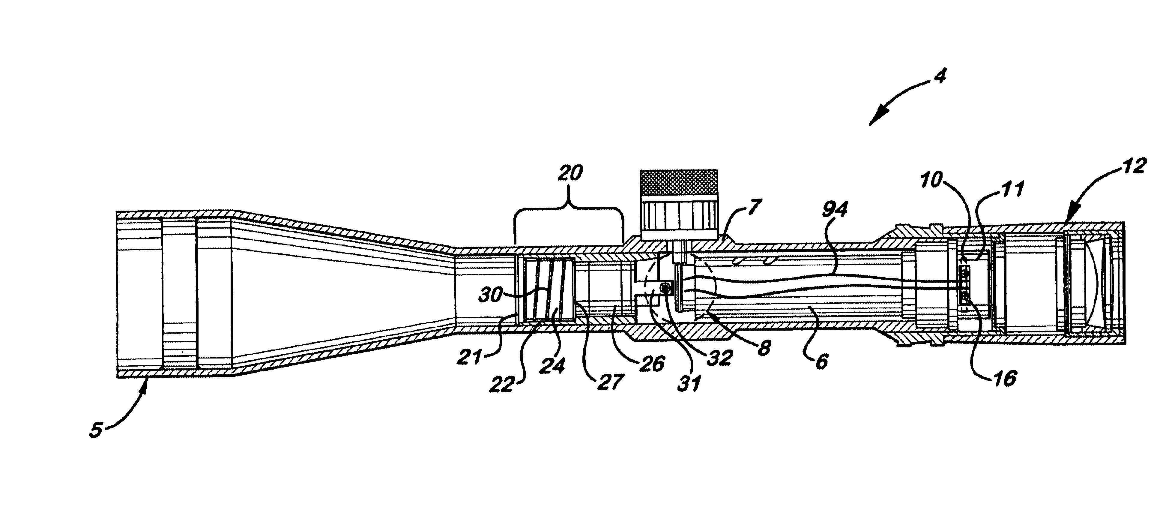
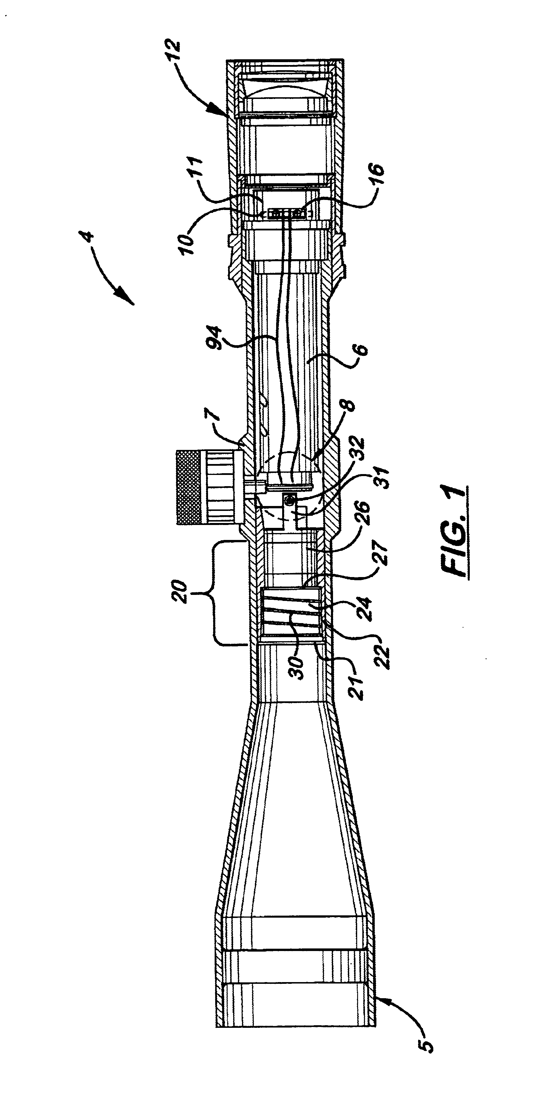
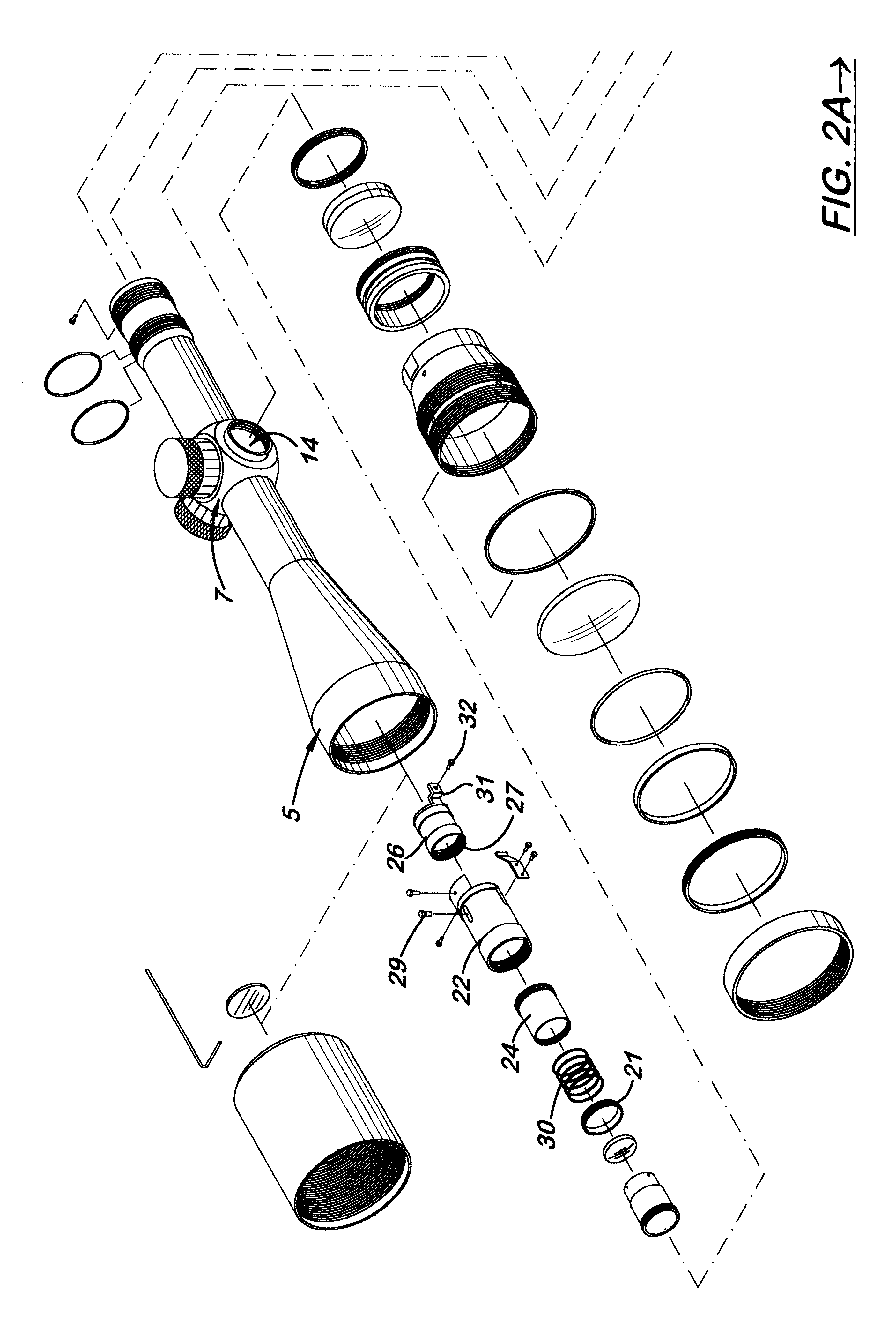
Referring to the accompanying Figs., there is shown and described a combined focus and reticle illumination system generally referenced as 4, for a riflescope 5 which uses a single, dual functioning turn knob 8 mounted on the scope turret 7 for focusing and activating and deactivating the scope illuminated reticle assembly 10. During use, the turn knob 8 may be rotated to adjust the relative position of the front cell assembly 20 located inside the riflescope 5. The turn knob 8 also has push-pull movement ability that is used to deactivate or activate, respectively, an LED 13 located in the sidewall of the reticle housing 11 immediately forward of the eyepiece 12. When the turn knob 8 is pushed or pulled, a circuit board 80, located inside the outer adaptor 53, disconnects and connects, respectively, to a battery 88 located inside the turn knob cap 90. Wires 94 connected at one end to the circuit board 80 extend back through the turret 7 and longitudinally along the sidewalls of th...


PUM


Abstract

A combined focus and reticle illumination system for a riflescope which uses a single, dual functioning turn knob mounted on the scope turret for focusing and activating and deactivating the illuminated reticle. During use, the turn knob is rotated to adjust the relative position of a sliding focusing cell assembly located inside the scope body in front of the erector tube. The reticle, attached to the proximal end of the erector tube, includes a side mounted LED. The turn knob has a push-pull movement and a battery located therein that disconnects and connects, respectively, the electric circuit. The sliding focusing cell includes a rigid outer housing that is resistant to bending and a rear sliding lens cell that is biased in a rearward direction to be self-centering during recoil. Wires extend from the turn knob to the LED along the scope sidewalls and are designed to preclude twisting.

Description

1. Field of the InventionThis invention pertains to riflescopes built with components having little tolerance to insure accuracy and more particularly, to scopes in which the activation and deactivation of the illumination reticles and the focusing operation of the lens are controlled by one turn knob.2. Description of the Related ArtRiflescopes with illuminated reticles that enable users to aim at targets at night or in dark environments are common. Typically, the reticles are etched into the distal end of the erector tube located inside the scope and inmmediately in front of the eyepiece. When a light source is provided with the reticle, it is positioned in a small housing built into the scope body adjacent to the distal end of the erector tube or eyepiece. Disposed inside the housing are a watch battery, combination on / off switch, and rheostat switch that controls activation and brightness. An outer cap with calibration markings printed on its outer surface is mounted over the ho...

Claims


Application Information

Patent Timeline
IPC IPC(8): G02B27/32G02B27/34
CPCG02B27/34
Inventor HUBER, JEFF
Owner LIGHTFORCE USA
Why Eureka
Try Eureka