Light source comprising a light-emitting element

a light-emitting element and light-emitting element technology, which is applied in the direction of discharge tube luminescnet screens, lighting and heating apparatuses, instruments, etc., can solve the problems of limited number of inorganic luminophores that meet these specifications, inefficient realization, and inability to realize emission colors, especially wide-band spectral colors

Inactive Publication Date: 2004-10-26
TOYODA GOSEI CO LTD
View PDF1 Cites 271 Cited by
  • Summary
  • Abstract
  • Description
  • Claims
  • Application Information

AI Technical Summary

Benefits of technology

The task of this invention is to alter a light source of the type mentioned at the outset so that white light colors with warmer color temperatures, especially those color locations that lie within the tolerance ellipses established by the CIE for general illumination may be created under conditions of high luminous efficiency and a high degree of color reproduction quality.

Problems solved by technology

Numerous emission colors, especially wide-band spectral colors, cannot be realized from LED's because of the intrinsic emission of an active semiconductor material, or can only be inefficiently realized.
However, there is only a limited number of inorganic luminophores that meet these specifications.
These, however, include the disadvantage that they possess a high degree of efficiency only at an emission maximum of less than 560 nm.
This results in severely-limited application possibilities.
The maximum of the emission from the Ba.sub.2 SiO.sub.4 :Eu.sup.2+ luminescent material is, however, 505 nm, so that white light cannot be reliably created using such a combination.

Method used


Image

  • Light source comprising a light-emitting element
  • Light source comprising a light-emitting element
  • Light source comprising a light-emitting element

Examples


embodiment examples

BEST EMBODIMENT EXAMPLES OF THE INVENTION

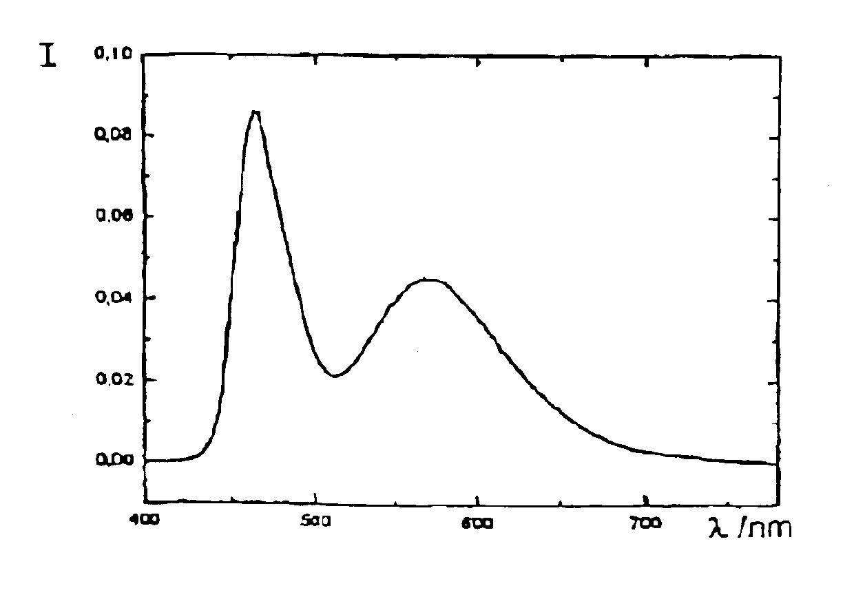
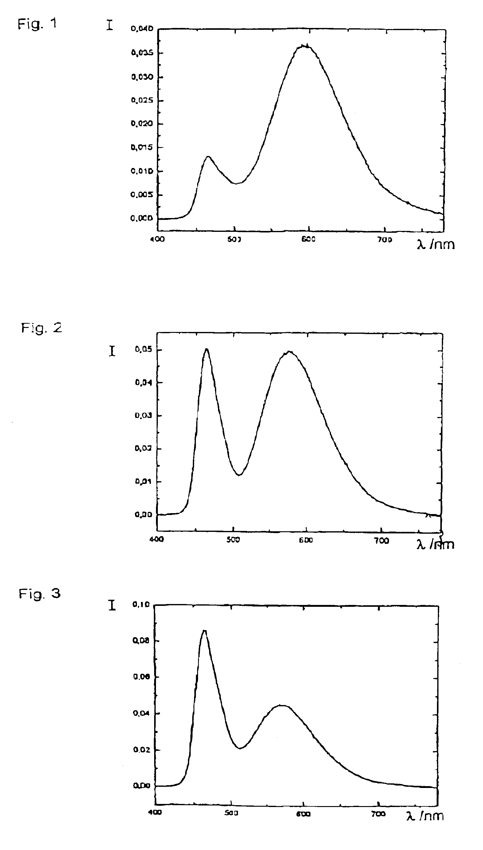
FIG. 1 shows the emission spectrum of a white LED with a color temperature of 2700 K that is formed by combination of a LED emitting blue light with effective wavelength of 464 nm with luminophore based on the invention of composition (Sr.sub.1.4 Ca.sub.0.6 SiO.sub.4 :Eu.sup.2+) that emits light in a second spectral region with a maximum value of 596 nm.

Further examples for the combination of an LED emitting light at 464 nm with one of the ortho-silicate luminophores are shown in FIGS. 2 and 3. If a yellow-emitting luminophore of composition (Sr.sub.1.90 Ba.sub.0.08 Ca.sub.0.02 SiO.sub.4 :Eu.sup.2+) is used for color conversion, a white-light color with color temperature of 4100 K may be set, but with use of the luminophore (Sr.sub.1.84 Ba.sub.0.16 SiO.sub.4 :Eu.sup.2+), for example, a white-light color with color temperature of 6500 K may be obtained.

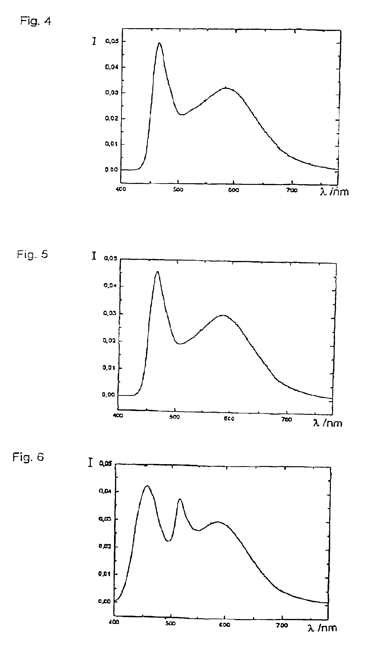
FIG. 4 shows the typical spectrum for the combination of a 464-nm LED with two ortho-silicat...


PUM

PropertyMeasurementUnit
Raaaaaaaaaaa
Raaaaaaaaaaa
Raaaaaaaaaaa

Abstract

The invention relates to a light source comprising a light-emitting element, which emits light in a first spectral region, and comprising a luminophore, which comes from the group of alkaline-earth orthosilicates and which absorbs a portion of the light emitted by the light source and emits light in another spectral region. According to the invention, the luminophore is an alkaline-earth orthosilicate, which is activated with bivalent europium and whose composition consists of: (2-x-y)SrOx(Ba, Ca)O(1-a-b-c-d)SiO2aP2O5bAl2O3cB2O3dGeO2:yEu<2+> and / or (2-x-y)BaOx((Sr, Ca)O(1-a-b-c-d)SiO2aP2O5bAl2O3cB2O3dGeO2:yEu<2+>. The desired color (color temperature) can be easily adjusted by using a luminophore of the aforementioned type. The light source can contain an additional luminophore selected from the group of alkaline-earth aluminates, activated with bivalent europium and / or manganese, and / or can contain an additional red-emitting luminophore selected from the group Y(V, P, Si)O4:Eu or can contain alkaline-earth magnesium disilicate.

Description

TECHNICAL REALMThe invention relates to a light source with a light-emitting element that emits in a first spectral realm, preferably in the blue and / or ultraviolet range of that visual spectrum, and with a luminophore that either is derived from the group of alkaline-earth ortho-silicates or that contains at least a component from this group of luminescent materials that absorbs a portion of the emission from the light-emitting element and then emits in another region of the spectrum, preferably in the yellow-green, yellow, or orange ranges. The luminophore selected may also be used in mixtures with other luminophores from this group and / or with other luminescent materials that do not belong to this group.The light-emitting element is preferably an inorganic light-emitting diode (LED), but may also be an organic LED, a laser diode, and inorganic thick-layer electro-luminescence film, or an inorganic thin-layer electro-luminescence component.STATE OF THE ARTInorganic LED's distingui...

Claims


Application Information

Patent Timeline
Patent Type & Authority Patents(United States)
IPC IPC(8): C09K11/77H01L33/00H01L33/50F21V9/40F21Y105/10F21Y115/10H01L33/06H01L33/32H05B33/20
CPCB82Y20/00C09K11/7721C09K11/7734C09K11/774C09K11/7795G02B6/0036G02B6/0073H01L33/502H01L2224/73265H01L2224/49107H01L2224/48257H01L25/0753H01L33/06H01L33/32H01L33/507H01L2933/0091Y02B20/181H01L2224/45139H01L2224/45144H01L2224/32257F21Y2101/02F21Y2105/001H01L2224/16145H01L2224/32245H01L2224/48091H01L2224/48247H01L2924/00014H01L2924/00F21Y2105/10F21Y2115/10H01L2924/181H01L2924/00011Y02B20/00C09K11/77344H01L2924/01049H01L2924/00012C09K11/77
Inventor TASCH, STEFANPACHLER, PETERROTH, GUNDULATEWS, WALTERKEMPFERT, WOLFGANGSTARICK, DETLEF
Owner TOYODA GOSEI CO LTD
Why Eureka
Try Eureka