
Photon energy conversion structure

Inactive Publication Date: 2009-10-29
WEPOWER TECH LLC
View PDF33 Cites 136 Cited by
  • Summary
  • Abstract
  • Description
  • Claims
  • Application Information

AI Technical Summary

Benefits of technology

[0031]An objective of the invention is to contribute to the reduction of greenhouse gases by reducing the amount of energy spent on artificial illumination.
[0034]Light sources according to the present invention reduce the power, efficiency, complexity, cost, and compromise to the greenhouse effect by using ultraviolet light emitting diodes as opposed to fluorescent light, incandescent light, and Halogen light.
[0035]An object of the invention is to provide an LED light source which provides high luminous efficiency with high color rendering. According to the invention, this can be accomplished by matching an appropriate multicolor phosphor and encapsulation material to the near ultraviolet (NUV) region, to obtain white LEDs with both high color rendering and high luminous efficacy. The high efficiency of white-light LEDs means that the active potential exists for enormous energy savings.

Problems solved by technology

One recognized problem with incandescent bulbs is that they are a very inefficient light source because most of the electrical energy applied to the incandescent light bulb is lost in heat instead of creating light.
Not only is this a waste of energy, but when used in locations where heat is not desired, such as in warm environments, additional power is consumed by AC systems to remove the additional heat resulting in more inefficiencies and waste.
However, much of the light emitted from such a source takes the form of long infrared heat wavelengths.
The light units can be even more confusing when you consider that some light sources, such as a common light bulb, launch light in all directions while others, such as a laser, concentrate the light into narrow beams.
Although such a method is efficient, the inductive current limiting scheme slows the rise and fall times of the discharge current through the tube and thus produces longer then desired light pulses.
The main factor that ultimately limits the modulation speed is the response time of the phosphor used inside the lamp.
Most visible phosphors will not allow pulsing much faster than about 500,000 pulses per second.
The visible light emitted by the typical “cool white” lamp is also not ideal when used with a silicon photo diode.
But, the large surface emitting areas of fluorescent lamps makes them impractical for long-range applications, since the light could not be easily collected and directed into a tight beam.
They are typically in the shape of a wound spiral, and many people have been reluctant to use them because they believe their shape is not esthetically pleasing.
Also, another downside is that fluorescent tubes contain toxic mercury vapor.
In the early 1990s, it has been reported that it cost $275 million annually to dispose of fluorescent tubes in an environmentally sound manner, greatly burdening the industry and its end users.
In recent years, there is a growing concern about the mercury which eventually pollutes the environment because it is a health hazard.
Rods are highly sensitive to light but are comprised of a single photo pigment, which accounts for the loss in ability to discriminate color.
However, many other man-made light emitters, such as fluorescent lamps and the yellow or blue / white street lamps, emit very little infrared light.
Of course, colored LEDs are not generally acceptable as a light source to replace white light incandescent and fluorescent lighting.
Several problems currently exist with white-light devices composed of blue LEDs and Ce3+-doped yttrium aluminum garnet (Ce:YAG) yellow phosphors that mix blue and yellow light to produce what appears to be white light.
These include the halo effect of blue / yellow color separation, strong temperature and current dependence of chromaticity, and poor color rendering caused by the lack of green and red components.

Method used


Image

  • Photon energy conversion structure
  • Photon energy conversion structure
  • Photon energy conversion structure

Examples


Embodiment Construction

[0056]One or more preferred embodiments of the invention will be described, but the embodiments are merely exemplary ways of implementing the invention and the invention is not limited to these exemplary embodiments.

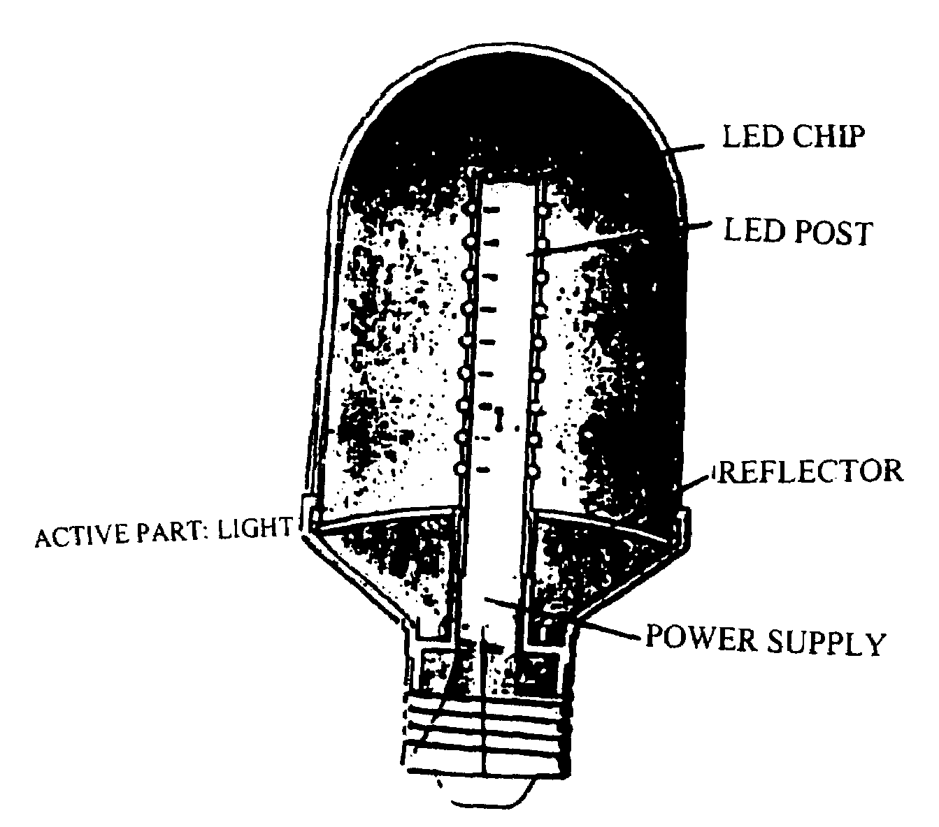
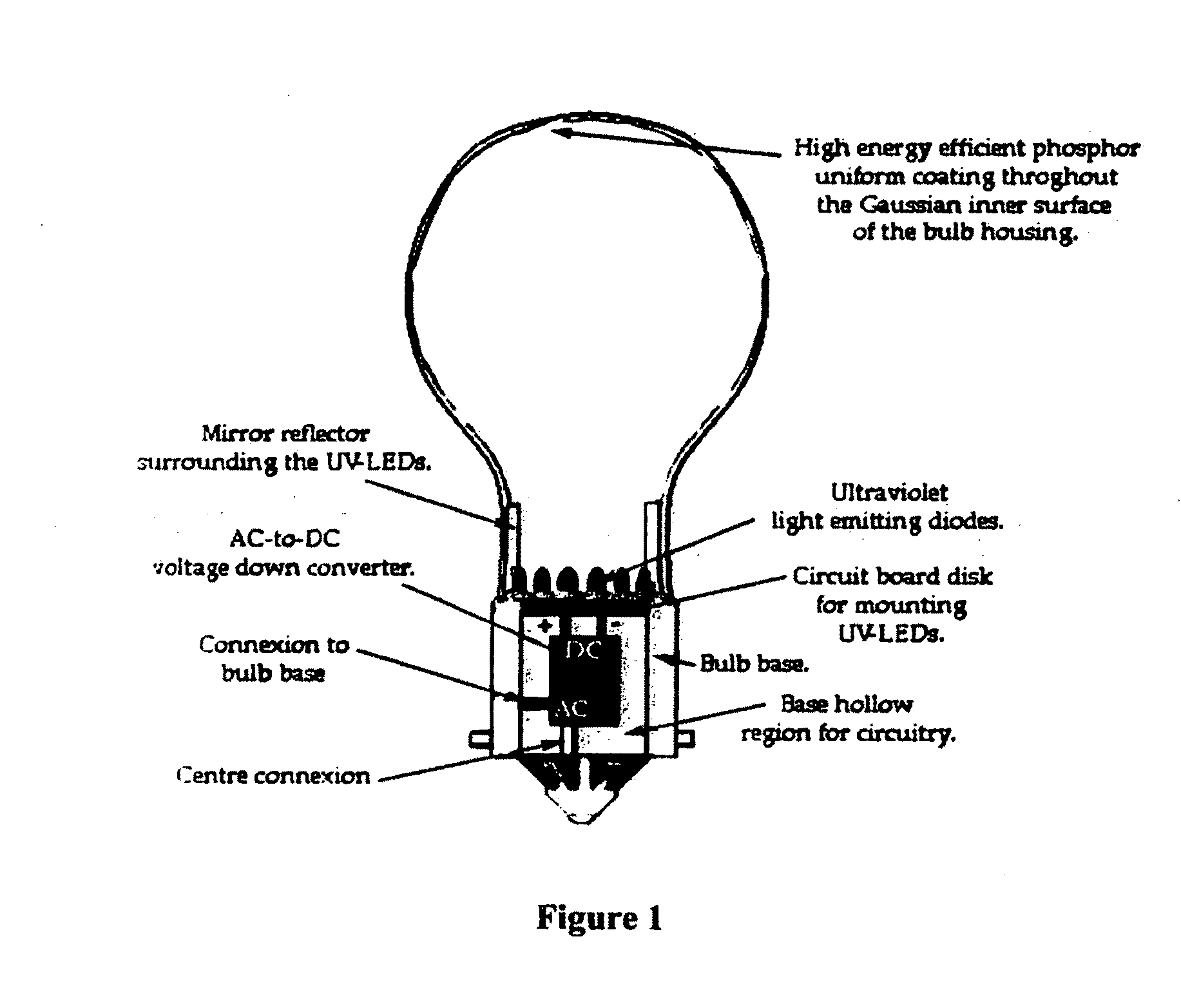
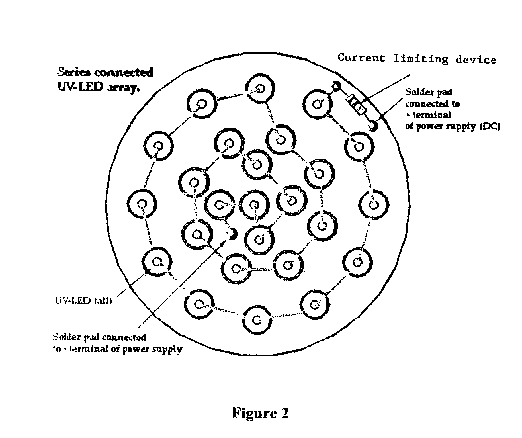
[0057]As shown in FIG. 1 one can incorporate currently manufactured, low cost, ultra-violet light emitting diodes of various UV wavelengths and situate the UV-LED and the voltage down converter(s) into a conventional light bulb design. This light bulb, which can either be made of glass or polycarbonate (non-breakable) will be coated with a thin film (uniform coating) of a high efficiency phosphor that can have a range of emitted colors for various applications and the shape of the light bulb can be conventional or any novel shape. Another advantage of this invention is that the bulb or other chosen novel shape does not need to be evacuated of ambient air.

[0058]Further if this bulb is designed to replace conventional fluorescent lights, in the form of long tubes or any ot...


PUM


Abstract

A photon energy conversion device uses at least one ultraviolet light emitting diode (UV-LED) with a wavelength shifting medium such as phosphor or quantum dots. The device can be used as a light source, and shaped like incandescent light bulbs, fluorescent tubes, circles or compact fluorescent bulbs.

Description

BACKGROUND OF THE INVENTION[0001]The present invention relates to structures using ultraviolet light emitting diodes (UV-LEDs), one example being a highly efficient solid state lighting source based on UV-LED and phosphor combinations. Such a structure can provide an UV-LED energy efficient light source for exact replacement of conventional incandescent light bulbs and fluorescent lighting systems.[0002]Another aspect of the invention is a solar panel which produces electrical energy in response to incoming photons.[0003]The invention also provides methods for improving the phosphor coating conversion efficiency in UV-LEDs, where the fundamental quenching mechanisms for phosphor coatings can be determined and quantified.[0004]For more than 100 years incandescent light bulbs have been using for providing light in homes, businesses and other structures. One recognized problem with incandescent bulbs is that they are a very inefficient light source because most of the electrical energy...

Claims


Application Information

Patent Timeline
IPC IPC(8): F21V7/00H01L33/00H01J1/62
CPCC09K11/778F21Y2101/02F21K9/52F21K9/61F21K9/64F21Y2115/10
Inventor DEAK, DAVID G.LAM, JOSEPH
Owner WEPOWER TECH LLC
Learn More