Integrated load impedance sensing for tunable matching networks

Active Publication Date: 2007-02-15
NOKIA TECHNOLOGLES OY
View PDF2 Cites 152 Cited by
  • Summary
  • Abstract
  • Description
  • Claims
  • Application Information

AI Technical Summary

Benefits of technology

[0020] the invented solution allows a reduction of the electromagnetic energy that is radiated from a tuneable impedance matching s

Problems solved by technology

For example, for a small size mobile communication device it is a very challenging task to realize a 6 cm transmission line having desired properties.
Furthermore, a transmission

Method used


Image

  • Integrated load impedance sensing for tunable matching networks
  • Integrated load impedance sensing for tunable matching networks
  • Integrated load impedance sensing for tunable matching networks

Examples


Example

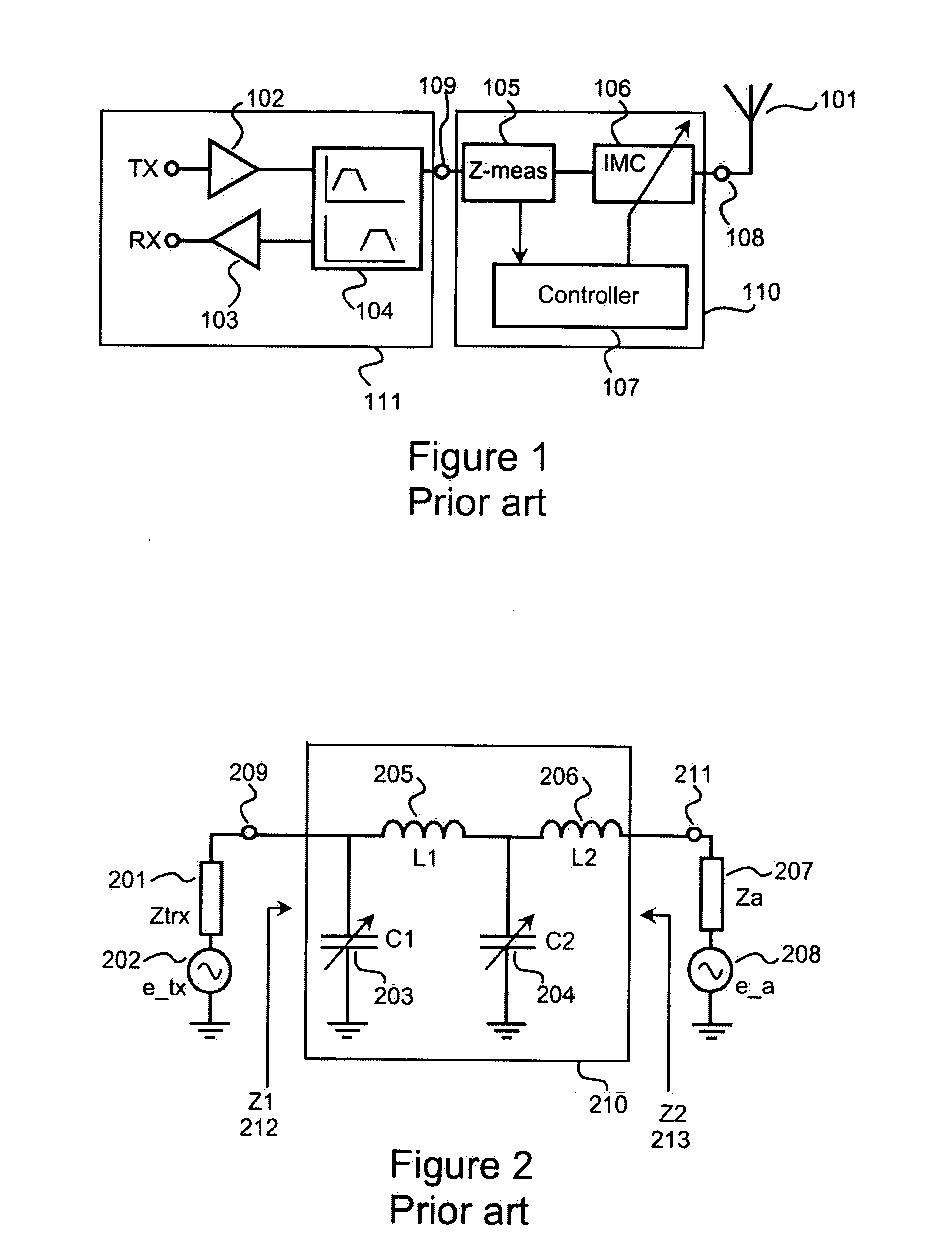
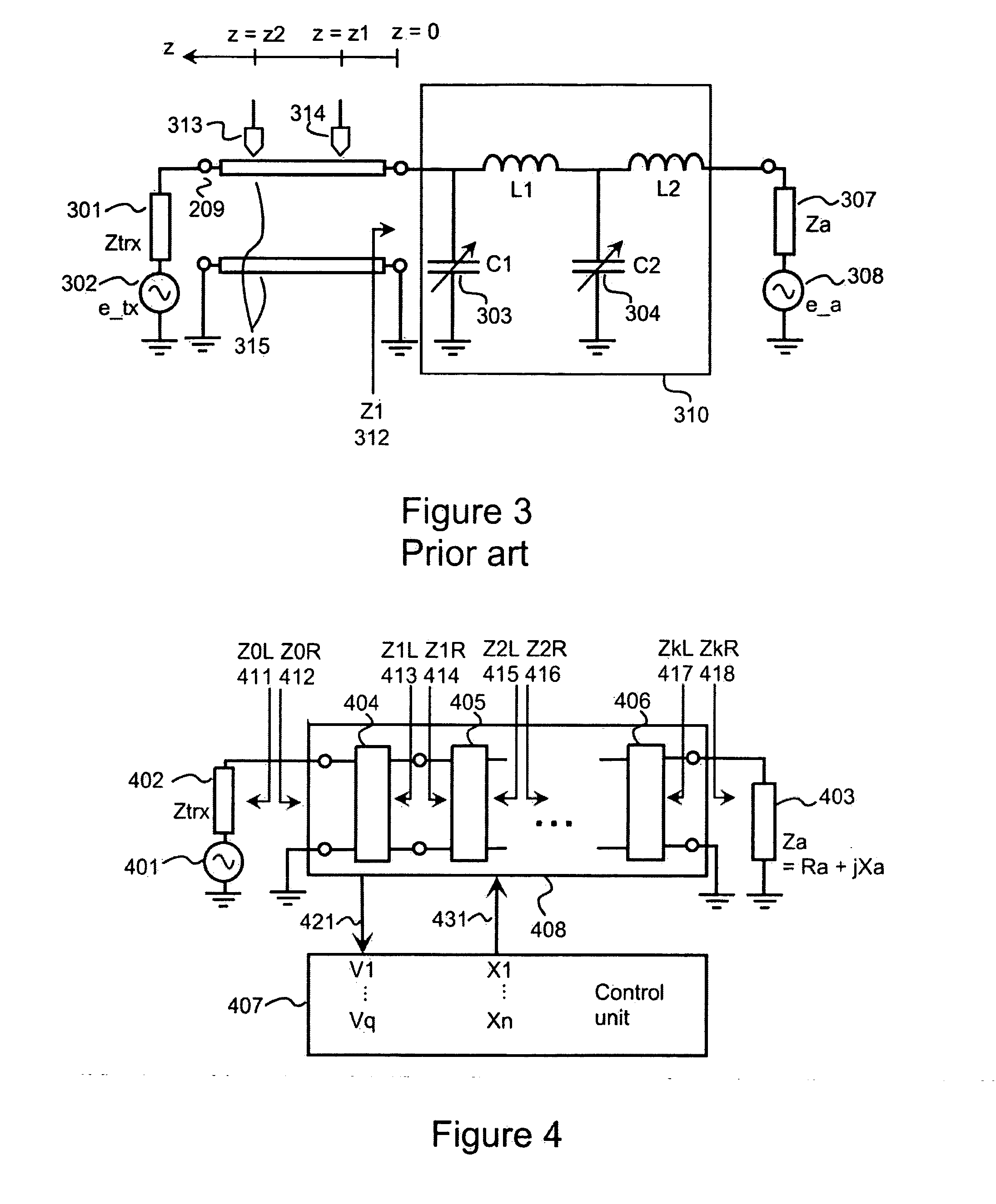
[0051]FIGS. 1-3 have been explained above in the description of the prior art.

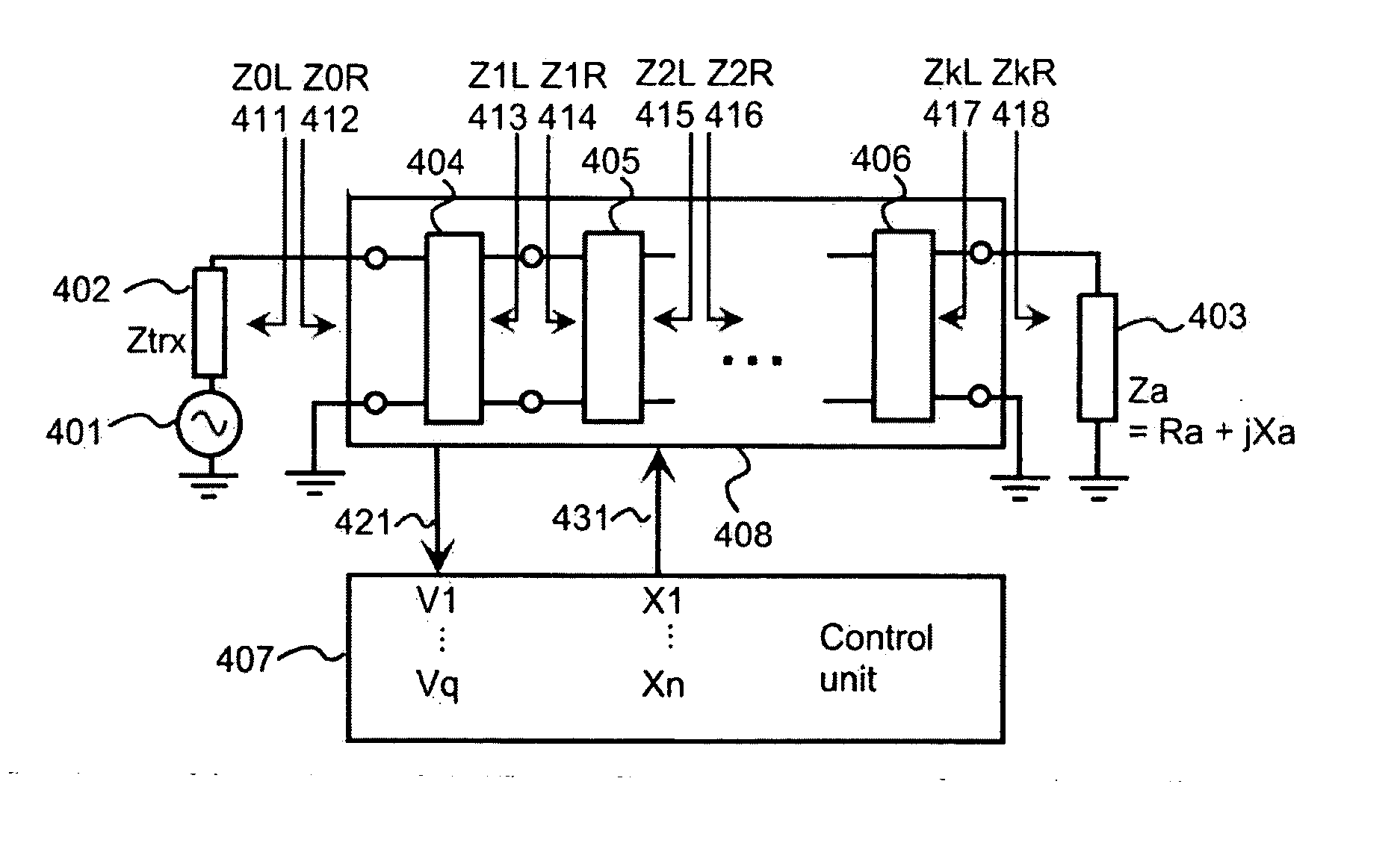
[0052]FIG. 4 shows a principle of a tuneable impedance matching system according to certain embodiments of the invention. The system is assumed to be energized only by a source voltage 401. The frequency at which the system is operating is assumed to be within a so narrow an interval that the system can be analyzed as if the operating frequency were constant. If there is also an electromotive force associated with a load impedance 403, the electromotive force at the load is assumed to be negligible compared with the source voltage 401. An impedance matching circuit 408 is presented as a chain of one or more four-pole circuits 404, 405, . . . , 406. A control unit 407 measures a set of voltages 421 from the impedance matching circuit 408. The control unit 407 comprises calculation means for solving a real part and an imaginary part of the load impedance 403 based on the set of measured voltages 421 and bas...


PUM


Abstract

An impedance matching system may be used, for example, for impedance matching between a transmitter/receiver front-end and an antenna in a mobile communication device. In a tuneable impedance matching system according to the invention a tuneable impedance matching circuit (508) is used also as a measuring circuit for obtaining a value of a load impedance. A real part and an imaginary part of a load impedance (503) is calculated based on voltages measured on nodes of the tuneable impedance matching circuit and on known component values of the tuneable impedance matching circuit. Values for adjustable electrical components (504, 505) of the tuneable impedance matching circuit are determined based on the obtained load impedance value and on an impedance matching condition.

Description

FIELD OF THE INVENTION [0001] The invention relates to tuneable impedance matching systems. An impedance matching system according to the invention may be used, for example, for impedance matching between a transmitter / receiver front-end and an antenna in a mobile communication device. BACKGROUND OF THE INVENTION [0002] In an electrical system maximum power transfer between a load and a source is achieved when impedances of the load and the source are matched with respect to each other, which minimizes reflection losses between the load and the source. For example, in a mobile communication device a characteristic impedance of a transmitter / receiver front-end is substantially constant but an antenna impedance varies considerably with frequency and with external circumstances. An example of an external circumstance that has an effect on the antenna impedance is positions of user's fingers in the vicinity of an antenna, i.e. an ‘finger effect’. In a mobile communication device an ante...

Claims


Application Information

Patent Timeline
IPC IPC(8): H03H7/38
CPCH03H7/38H04B1/18H04B1/0458
Inventor RANTA, TERO
Owner NOKIA TECHNOLOGLES OY
Why Eureka
Try Eureka