Front feed microwave antenna

a microwave antenna and front-feed technology, applied in the field of antennas, can solve the problems of uncertain energy loss, difficult manufacturing and costly of metal paraboloids, complicated and costly procedures, etc., and achieve the effect of reducing reflection loss, improving convergence performance of antennas, and avoiding electromagnetic energy reduction

Active Publication Date: 2014-10-30
KUANG CHI INNOVATIVE TECH
View PDF4 Cites 4 Cited by
  • Summary
  • Abstract
  • Description
  • Claims
  • Application Information

AI Technical Summary

Benefits of technology

[0021]Implementation of the technical solution of the present invention brings the following beneficial effects: by designing the refractive index change on a core layer and a graded layer of a metamaterial panel and between them, an electromagnetic wave emitted by an emission source is converted into a planar wave after being refracted twice, thereby improving convergence performance of the antenna, decreasing reflection loss significantly, avoiding decrease of electromagnetic energy, increasing the transmission distance, and improving antenna performance. Further, a metamaterial with a divergence function is arranged in front of the emission source, which increases the short-distance emission scope of the emission source, so that the overall dimensions of the feed-forward microwave antenna become less, and the electromagnetic wave reflected back by the core layer bypasses the emission source without generating any emission source shadow and causing energy loss. Further, an artificial metal microstructure or artificial pore structure to make up the metamaterial in the present invention, which brings beneficial effects of a simple process and low costs.

Problems solved by technology

However, the feed-forward microwave antenna in the prior art has the following shortcomings: one is that a part of electromagnetic waves reflected by the metal paraboloid is blocked by the emission source which leads to a certain energy loss, and another one is that the metal paraboloid is difficult to manufacture and costly.
The procedure is complicated and costly, and the shape of the paraboloid needs to be accurate enough to implement directional propagation of the antenna, which hence imposes high requirements on processing precision.
This method makes the cutting very precise, but it is difficult to manufacture such a large CNC machine tool, which is costly.

Method used


Image

  • Front feed microwave antenna
  • Front feed microwave antenna
  • Front feed microwave antenna

Examples


first embodiment

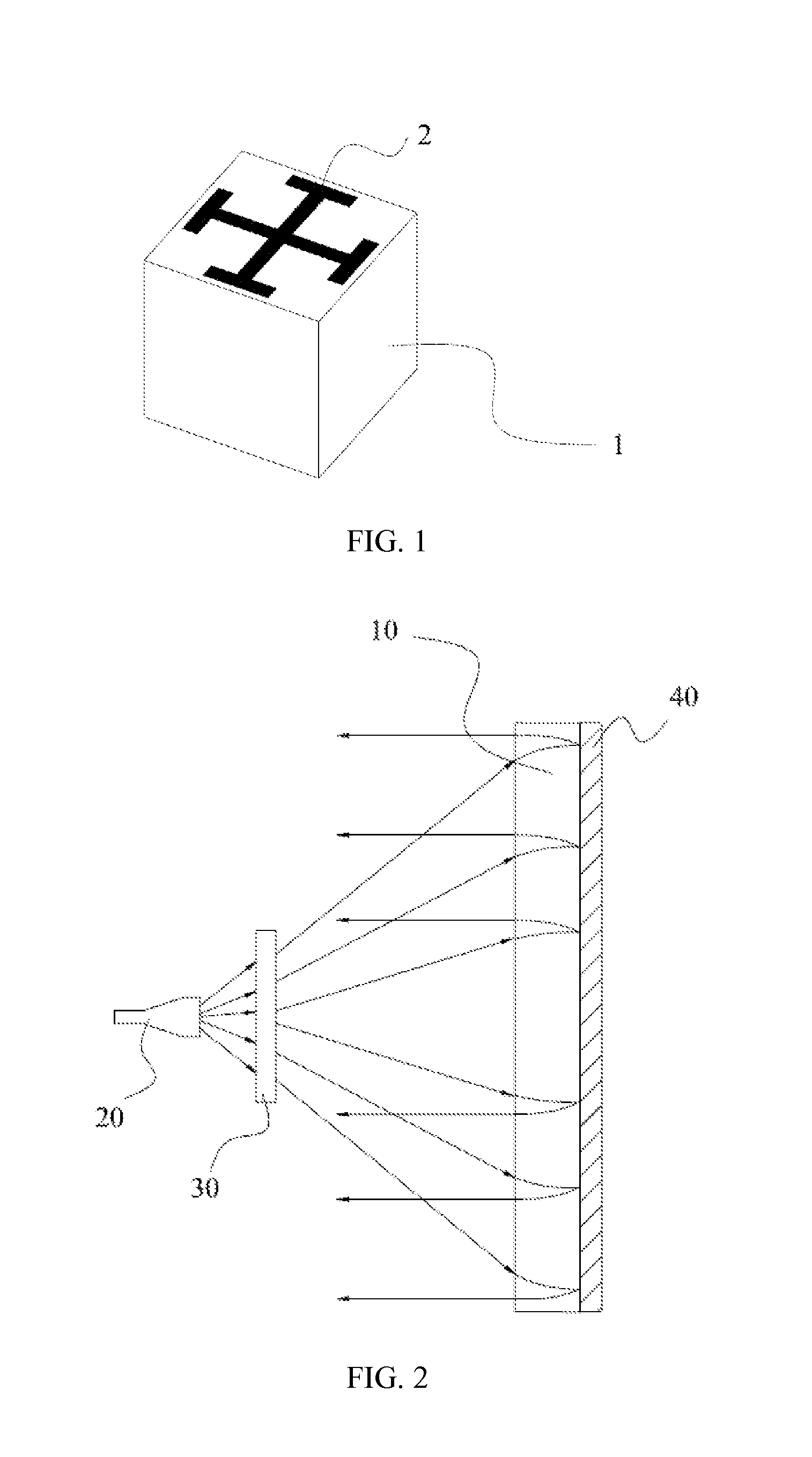
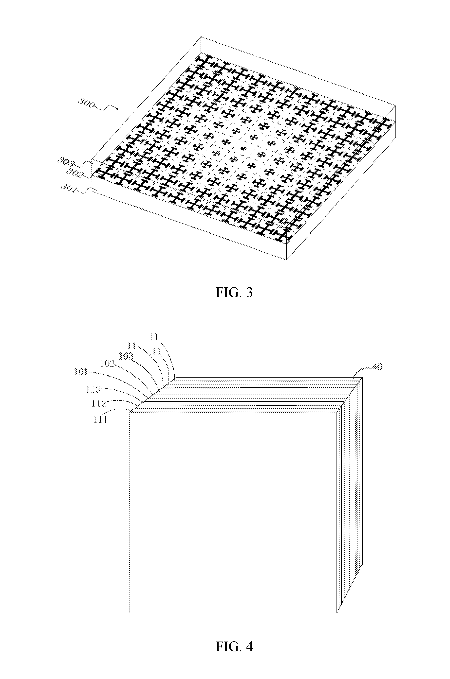
[0038]Referring to FIG. 1, a schematic, isometric structural diagram of a basic unit that makes up a metamaterial according to the present invention is shown. The basic unit of the metamaterial includes an artificial microstructure 1 and a substrate 2 to which the artificial microstructure is attached. In the present invention, the artificial microstructure is an artificial metal microstructure. The artificial metal microstructure has a planar or three-dimensional topology structure that can respond to an electric field or a magnetic field of an incident electromagnetic wave. Once the pattern or dimensions of the artificial metal microstructure on each basic unit of the metamaterial is changed, the response of each basic unit of the metamaterial to the incident electromagnetic wave can be changed. When multiple basic units of the metamaterial are arranged according to a specific law, the metamaterial can make a macro response to the electromagnetic wave. Because the metamaterial as ...

second embodiment

[0054]Referring to FIG. 10, a schematic isometric structural view of a basic unit that makes up a metamaterial according to the present invention is shown. The basic unit of the metamaterial includes a substrate 2′ and a plurality of artificial holes 1′ defined in the substrate 2′. The artificial holes 1′ defined in the substrate 2′ cause the permittivity and the permeability at each point of the substrate 2′ to vary with the volume of the artificial holes 1′, so that each basic unit of the metamaterial has a different electromagnetic response to the incident wave with a same frequency. When the basic units of the metamaterial are arranged according to a specific law, the metamaterial can make a macro response to the electromagnetic wave. Because the metamaterial as an entirety needs to have a macro electromagnetic response to the incident electromagnetic wave, responses made by the basic units of the metamaterial to the incident electromagnetic wave need to be continuous. This requ...


PUM


Abstract

A front feed microwave antenna, which comprises a radiation source, a first metamaterial panel used for radiating an electromagnetic wave emitted by the radiation source, a second metamaterial panel, and a reflective panel affixed to the back of the first metamaterial panel. The electromagnetic wave is emitted via the first metamaterial panel, refracted by entering the second metamaterial panel, reflected by the reflective panel, and finally re-refracted by reentering the second metamaterial panel, then finally parallel-emitted. Employment of the principle of metamaterial for manufacturing the antenna allows the antenna to break away from restrictions of conventional concave lens shape, convex lens shape, and parabolic shape, thereby allowing the shape of the antenna to be panel-shaped or any shape as desired, while allowing for reduced thickness, reduced size, facilitated processing and manufacturing, reduced costs, and improved gain effect.

Description

TECHNICAL FIELD[0001]The present invention relates to the field of antennas, and in particular, to a feed-forward microwave antenna.BACKGROUND[0002]A feed-forward microwave antenna in the prior art is generally formed of a metal paraboloid and an emission source located at a focus of the metal paraboloid, where the metal paraboloid serves a purpose of reflecting an external electromagnetic wave to the emission source or reflecting an electromagnetic wave emitted by the emission source to outside. An area of the metal paraboloid and the processing precision of the metal paraboloid directly decide various parameters of the microwave antenna, such as gain and directivity.[0003]However, the feed-forward microwave antenna in the prior art has the following shortcomings: one is that a part of electromagnetic waves reflected by the metal paraboloid is blocked by the emission source which leads to a certain energy loss, and another one is that the metal paraboloid is difficult to manufactur...

Claims


Application Information

Patent Timeline
Patent Type & Authority Applications(United States)
IPC IPC(8): H01Q19/06H01Q19/10
CPCH01Q19/10H01Q19/06H01Q15/0086H01Q15/10H01Q15/23H01Q19/065
Inventor LIU, RUOPENGJI, CHUNLINYUE, YUTAOYIN, XIAOMING
Owner KUANG CHI INNOVATIVE TECH
Why Eureka
Try Eureka