A/D converter having a dynamic encoder

a converter and encoder technology, applied in the field of analogtodigital converters (a/d converters) having a dynamic encoder, can solve the problems of limiting the conversion rate of a/d converters, reducing the conversion rate or conversion speed thereof in proportion to the increase of the number of bits of input thermometric codes, and achieving errors within 1-bit levels

Inactive Publication Date: 2001-05-15
NEC ELECTRONICS CORP
View PDF10 Cites 156 Cited by
  • Summary
  • Abstract
  • Description
  • Claims
  • Application Information

AI Technical Summary

Problems solved by technology

That is, the conventional A / D converter achieves an error within 1-bit level after the error correction.
The conventional flash A / D converter using a dichotomizing search technique as described above, however, has a problem in that the conversion rate or conversion speed thereof reduces in proportion to the increase of the number of bits of the input thermometric code.
In other words, N-bit code of the output digital signal requires N times for search by the A / D converter because of the inter-bit dependency in the dichotomizing search technique, which limits the conversion rate of the A / D converter.
The conventional A / D converter has another problem in that the circuit scale and the power dissipation thereof increases with the increase of the number (N) of bits to be converted.

Method used


Image

  • A/D converter having a dynamic encoder
  • A/D converter having a dynamic encoder
  • A/D converter having a dynamic encoder

Examples


first embodiment

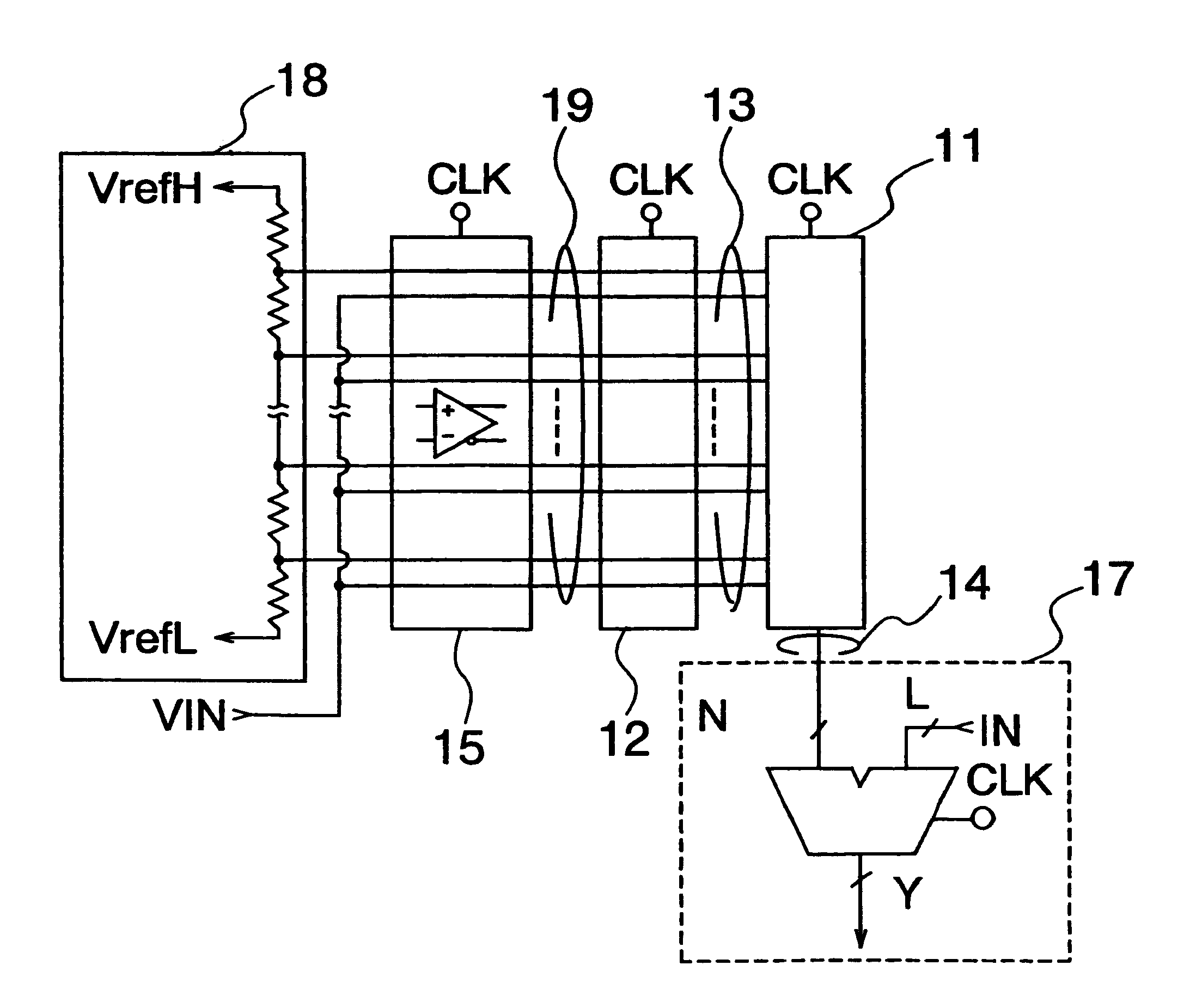
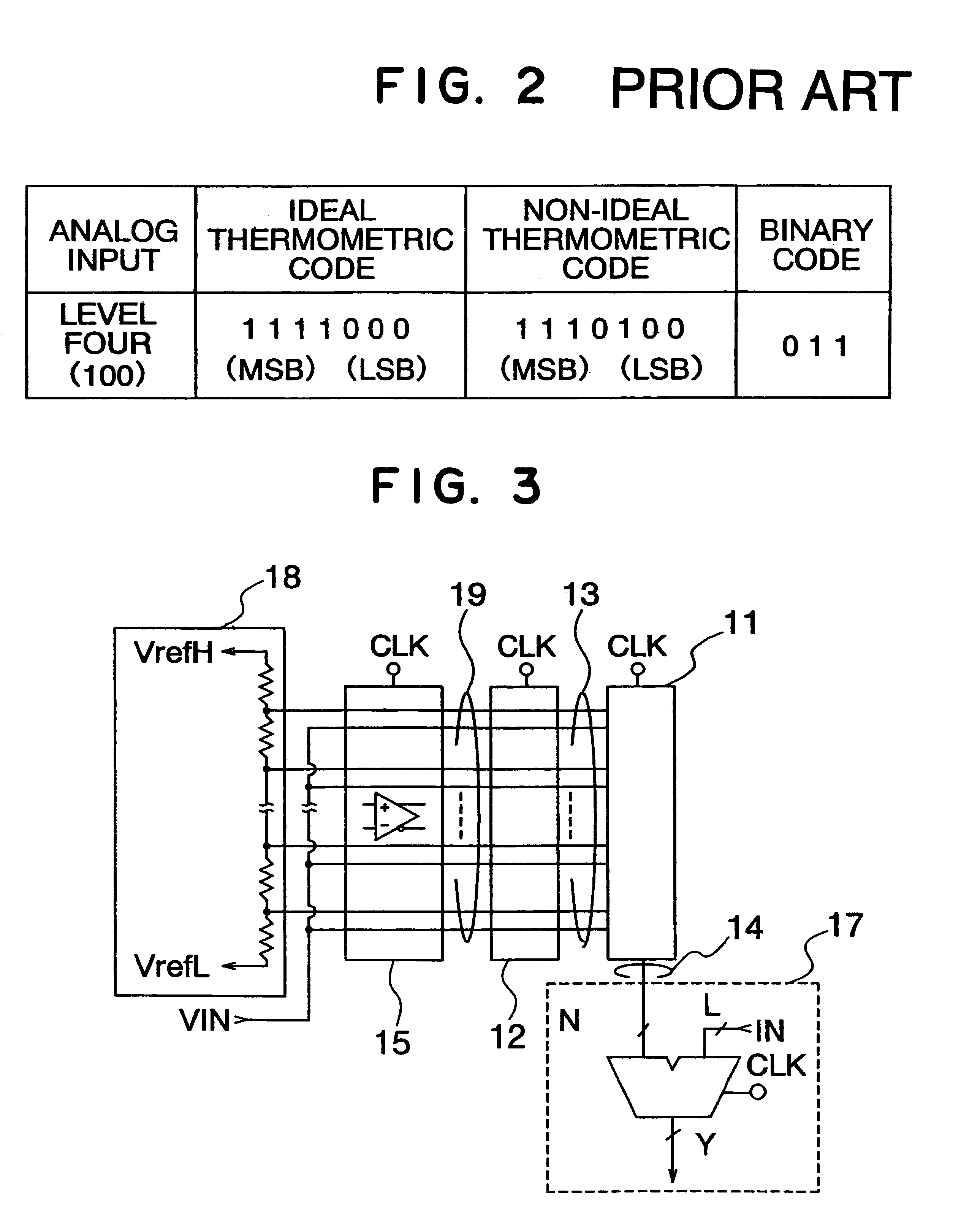
Referring to FIG. 5, an A / D converter according to the present invention has a resistor ladder 18 having a plurality (seven in this example) of nodes between each adjacent two of eight resistors R1 and connected between source lines V.sub.refH and V.sub.refL, a comparator array 15 including an array of comparators 151 to 157 each for comparing an input analog signal V.sub.IN against a corresponding reference voltage supplied from a corresponding node of the resistor ladder 18, a level converter array 12 including an array of level converters 161 to 167 each corresponding to one of the comparators 151 to 157 for outputting a complementary thermometric code 13, and a dynamic encoder 11 for encoding the complementary thermometric code 13.

Each of the level converters (or sense amplifiers) 161 to 167 is implemented by a differential circuit activated by the clock signal CLK for amplifying a small amplitude differential signal output from a corresponding one of the comparators 151 to 157....

third embodiment

Referring to FIG. 8, a dynamic encoder 11B in an A / D converter according to the present invention has an array of complementary signal generators 40, and an encoding section, precharge section and bit lines similar to those shown in FIG. 7. The complementary signal generators 40 have a dynamic configuration and receive outputs, which assume a high level when the input analog signal is higher than the respective reference voltages, from the level converter array 12. Referring to FIG. 9, the complementary signal generator 40 includes an inverter 43 and a pair of AND gates 41 and 42. The AND gate 41 receives the clock signal CLK and an output IT from the level converter 12 to output a non-inverting thermometric code bit OT, whereas the AND gate 42 receives an output from the inverter 43 receiving output IT from the level converter 12 to output an inverting thermometric code bit OB.

Referring to FIG. 10 showing the signal timing chart of the complementary signal generator 40 shown in FIG...


PUM


Abstract

An A/D converter includes a resistor ladder for generating a plurality of reference potentials, a comparing section for comparing each of the reference potentials against an input analog signal to output a thermometric code, and a dynamic encoder composed of a combinational circuit to encode the thermometric code to a binary code by responding a clock signal. The A/D conversion is finished in a single clock cycle at a high speed, with a reduced number of elements and reduced power dissipation.

Description

(a) Field of the InventionThe present invention relates to an analog-to-digital converter (A / D converter) having a dynamic encoder and, more particularly to an A / D converter having a dynamic encoder for encoding a thermometric code into a binary code.(b) Description of the Related ArtA / D converter is widely used to converting an input analog signal to a digital code which can be processed by a computer system. Referring to FIG. 1 showing a conventional A / D converter called a flash A / D converter in JP-A-8-36466 (from Texas Instrument), wherein an input analog signal of a thermometric code is directly converted by using a dichotomizing search technique to output a binary code without generating an intermediate code. The flash A / D converter includes a comparator array 51 including a plurality of comparators 52, and dichotomizing search encoder 53 including a plurality of D-flip-flops 54 and 56, and a plurality of multiplexers 55. The A / D converter has an advantage of reduction of the m...

Claims


Application Information

Patent Timeline
Patent Type & Authority Patents(United States)
IPC IPC(8): H03M1/06H03M1/08H03M1/36G06F3/05H03M7/16
CPCH03M1/365H03M1/0863
Inventor NAKAIGAWA, SACHIO
Owner NEC ELECTRONICS CORP
Why Eureka
Try Eureka