Method Of Patterned Plasma-Mediated Laser Trephination Of The Lens Capsule And Three Dimensional Phaco-Segmentation

a laser trephination and lens capsule technology, applied in the field of ophthalmic surgical procedures and systems, can solve the problems of difficult, if not impossible, formation of lens capsules using conventional, purely manual techniques, etc., and achieve the effects of reducing the duration of the procedure, reducing the risk of capsule opening and hard nucleus fragmentation, and increasing the precision of the procedur

Inactive Publication Date: 2010-07-29
AMO DEVMENT
View PDF91 Cites 159 Cited by
  • Summary
  • Abstract
  • Description
  • Claims
  • Application Information

AI Technical Summary

Benefits of technology

[0009]The techniques and system disclosed herein provide many advantages. Specifically, rapid and precise openings in the lens capsule and fragmentation of the lens nucleus and cortex is enabled using 3-dimensional patterned laser cutting. The duration of the procedure and the risk associated with opening the capsule and fragmentation of the hard nucleus are reduce, while increasing precision of the procedure. The removal of a lens dissected into small segments is performed using a patterned laser scanning and just a thin aspiration needle. The removal of a lens dissected into small segments is performed using patterned laser scanning and using a ultrasonic emulsifier with a conventional phacoemulsification technique or a technique modified to recognize that a segmented lens will likely be more easily removed (i.e., requiring less surgical precision or dexterity) and / or at least with marked reduction in ultrasonic emulsification power, precision and / or duration. There are surgical approaches that enable the formation of very small and geometrically precise opening(s) in precise locations on the lens capsule, where the openings in the lens capsule would be very difficult if not impossible to form using conventional, purely manual techniques. The openings enable greater precision or modifications to conventional ophthalmic procedures as well as enable new procedures. For example, the techniques described herein may be used to facilitate anterior and / or posterior lens removal, implantation of injectable or small foldable IOLs as well as injection of compounds or structures suited to the formation of accommodating IOLs.
[0010]Another procedure enabled by the techniques described herein provides for the controlled formation of a hemi-circular or curvilinear flap in the anterior lens surface. Contrast to conventional procedures which require a complete circle or nearly complete circular cut. Openings formed using conventional, manual capsulorhexis techniques rely primarily on the mechanical shearing properties of lens capsule tissue and uncontrollable tears of the lens capsule to form openings. These conventional techniques are confined to the central lens portion or to areas accessible using mechanical cutting instruments and to varying limited degrees utilize precise anatomical measurements during the formation of the tears. In contrast, the controllable, patterned laser techniques described herein may be used to create a semi-circular capsular flap in virtually any position on the anterior lens surface and in virtually any shape. They may be able to seal spontaneously or with an autologous or synthetic tissue glue or other method. Moreover, the controllable, patterned laser techniques described herein also have available and / or utilize precise lens capsule size, measurement and other dimensional information that allows the flap or opening formation while minimizing impact on surrounding tissue. The flap is not limited only to semi-circular but may be any shape that is conducive to follow on procedures such as, for example, injection or formation of complex or advanced IOL devices or so called injectable polymeric or fixed accommodating IOLs.

Problems solved by technology

There are surgical approaches that enable the formation of very small and geometrically precise opening(s) in precise locations on the lens capsule, where the openings in the lens capsule would be very difficult if not impossible to form using conventional, purely manual techniques.
These conventional techniques are confined to the central lens portion or to areas accessible using mechanical cutting instruments and to varying limited degrees utilize precise anatomical measurements during the formation of the tears.

Method used


Image

  • Method Of Patterned Plasma-Mediated Laser Trephination Of The Lens Capsule And Three Dimensional Phaco-Segmentation
  • Method Of Patterned Plasma-Mediated Laser Trephination Of The Lens Capsule And Three Dimensional Phaco-Segmentation
  • Method Of Patterned Plasma-Mediated Laser Trephination Of The Lens Capsule And Three Dimensional Phaco-Segmentation

Examples


Embodiment Construction

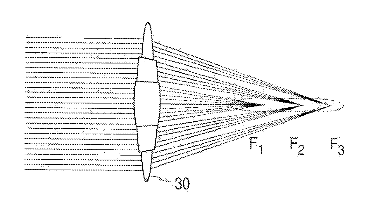
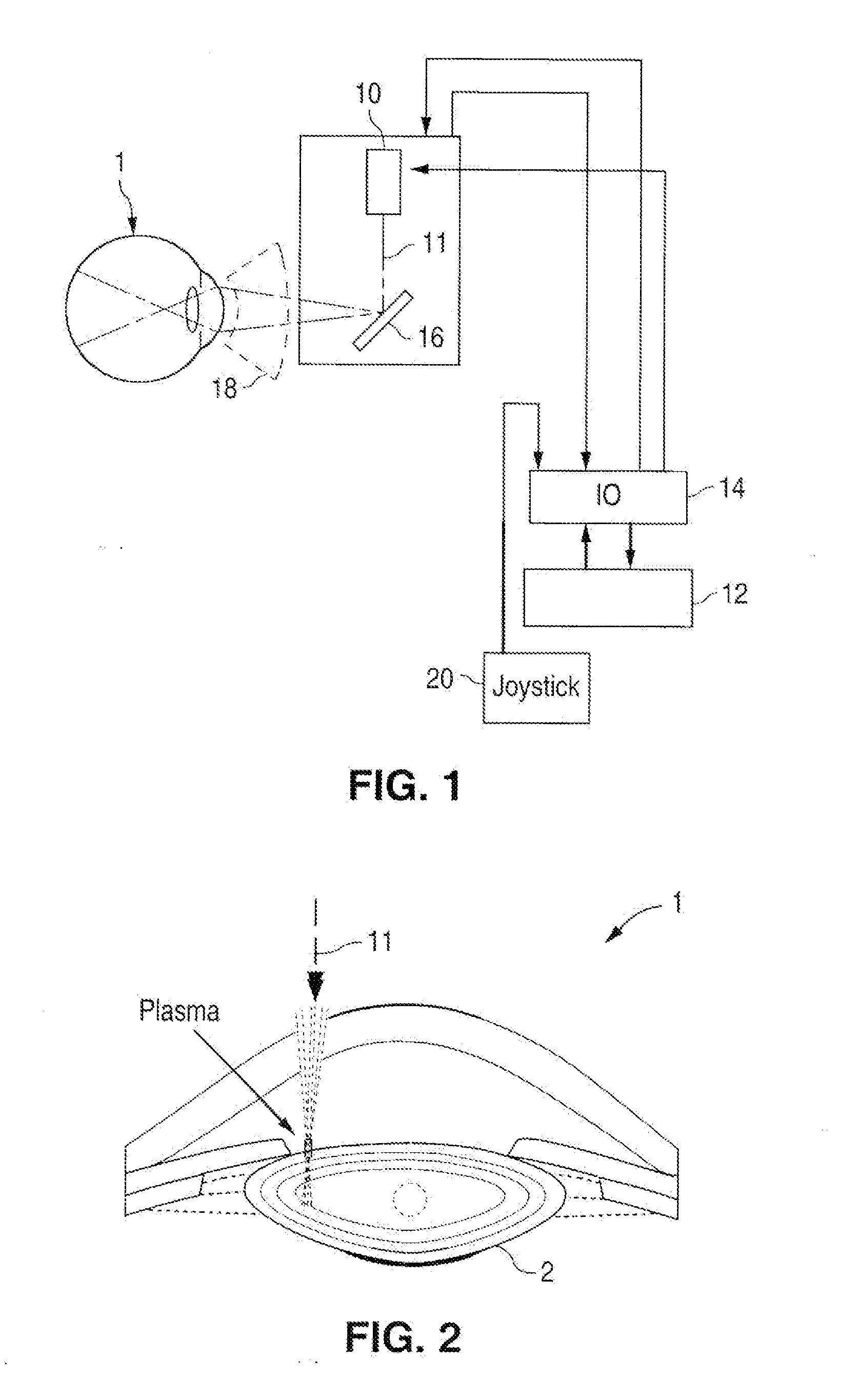
[0045]The present invention can be implemented by a system that projects or scans an optical beam into a patient's eye 1, such as the system shown in FIG. 1. The system includes a light source 10 (e.g. laser, laser diode, etc.), which may be controlled by control electronics 12, via an input and output device 14, to create optical beam 11 (either cw or pulsed). Control electronics 12 may be a computer, microcontroller, etc. Scanning may be achieved by using one or more moveable optical elements (e.g. lenses, gratings, or as shown in FIG. 1 a mirror(s) 16) which also may be controlled by control electronics 12, via input and output device 14. Mirror 16 may be tilted to deviate the optical beam 11 as shown in FIG. 1, and direct beam 11 towards the patient's eye 1. An optional ophthalmic lens 18 can be used to focus the optical beam 11 into the patient's eye 1. The positioning and character of optical beam 11 and / or the scan pattern it forms on the eye may be further controlled by use ...


PUM


Abstract

System and method for making incisions in eye tissue at different depths. The system and method focuses light, possibly in a pattern, at various focal points which are at various depths within the eye tissue. A segmented lens can be used to create multiple focal points simultaneously. Optimal incisions can be achieved by sequentially or simultaneously focusing lights at different depths, creating an expanded column of plasma, and creating a beam with an elongated waist.

Description

[0001]This application is a divisional of application Ser. No. 11 / 328,970, filed on Jan. 9, 2006, which claims the benefit of U.S. Provisional Application No. 60 / 643,056, filed Jan. 10, 2005.FIELD OF THE INVENTION[0002]The present invention relates to ophthalmic surgical procedures and systems.BACKGROUND OF THE INVENTION[0003]Cataract extraction is one of the most commonly performed surgical procedures in the world with estimates of 2.5 million cases being performed annually in the United States and 9.1 million cases worldwide. This is expected to increase to approximately 13.3 million cases by 2006 globally. This market is composed of various segments including intraocular lenses for implantation, viscoelastic polymers to facilitate surgical maneuvers, disposable instrumentation including ultrasonic phacoemulsification tips, tubing, and various knives and forceps. Modern cataract surgery is typically performed using a technique termed phacoemulsification in which an ultrasonic tip ...

Claims


Application Information

Patent Timeline
Patent Type & Authority Applications(United States)
IPC IPC(8): A61B18/18
CPCA61F9/00736A61F9/00812A61F9/00838A61F9/009A61F2009/00851A61F2009/0087A61F2009/00887A61F2009/00889A61F2009/00897A61F9/00831A61F2009/00895A61B18/20A61F2/1602A61F9/00825A61F2009/00882A61F9/008A61F9/00836A61F9/0084A61F2009/00844A61F9/00754A61F9/00814A61F9/00834A61F2009/00878A61B90/361A61B2018/00577A61F2009/00865
Inventor BLUMENKRANZ, MARK S.PALANKER, DANIEL V.ANDERSEN, DAN E.
Owner AMO DEVMENT
Why Eureka
Try Eureka