
Optical slider for input devices

a technology of input device and slider, which is applied in the direction of instruments, cathode-ray tube indicators, electric digital data processing, etc., can solve the problems of disturbing others and annoying users, and achieve the effects of reducing power consumption, limiting power requirements, and reducing the length of the light path

Inactive Publication Date: 2007-01-25
LOGITECH EURO SA
View PDF14 Cites 156 Cited by
  • Summary
  • Abstract
  • Description
  • Claims
  • Application Information

AI Technical Summary

Benefits of technology

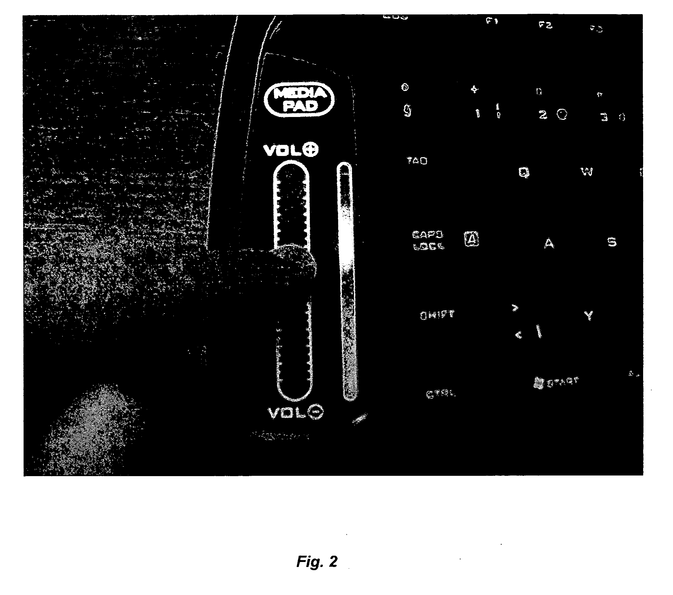
[0023] In one embodiment, the invention uses an optical solid state sensor, with at least some of the optical element using visible light so that the same light emitters are used for both sensing and user feedback, reducing power consumption. In other embodiments, the length of the light path is reduced, to limit the power requirements, by either the use of a lens, reflection (rather than transmission breaking) detection, light pipes and geometries which place the emitter close to the detector (such as interleaved emitters and detectors). An interleaved design puts both the emitters and detectors below the optical window, instead of on either side as in the prior art.
[0024] In embodiments of the invention used for scrolling / zooming, it has been recognized that the high resolution of prior art touch screens is not needed. Thus, reduced resolution is provided, with a significant reduction in cost and power requirements. A line of less than 20 interleaved emitters and detectors may be used in one embodiment, such as 8 emitters and 8 detectors.

Problems solved by technology

Many existing solid state sensors provide an acoustic feedback, which can be disturbing to others and annoying to the user.

Method used


Image

  • Optical slider for input devices
  • Optical slider for input devices
  • Optical slider for input devices

Examples


Embodiment Construction

[0043] The above application Ser. No. 10 / 025,838, incorporated by reference, includes the following description of an optical scrolling sensor for a mouse: “In another implementation, the finger rests in a trench wide enough to accommodate the finger, but not too wide in order to guide the finger in the direction of detection. Position detection is achieved with help of an array of light sources, or a single distributed light source, on one of the trench sides, and an array of light detectors located on the other side. Presence of the finger in the trench is detected from the reduced response in the detector directly facing the finger, or from combining responses from all detectors and determining by interpolation its minimum. In another method, the presence of the finger can be determined based on the differences of measured values over time (i.e., when no finger was there). Alternatively, a binary response from the light detector, either absolute (“light is above or below a given ...


PUM


Abstract

An optical feedback mechanism corresponding to a variation in input by a user's digit on an input element. The variation in input can be movement by the user's finger, or a change in the amount of pressure or force applied to a button. In one embodiment, the optical feedback is a linear light array adjacent a solid-state scroll / zoom sensor, with the light corresponding to the finger position. Alternately, a solid state button could provide feedback corresponding to the amount of pressure in the form of a change in intensity, color or blinking. In one embodiment, the input signal from an input element alternates between a scroll, zoom and / or other functions depending on the current application.

Description

CROSS-REFERENCES TO RELATED APPLICATIONS [0001] This patent application is a non-provisional of and claims the benefit of U.S. Provisional Patent Application No. 60 / 722,180, filed on Sep. 29, 2005, and is a continuation-in-part of U.S. patent application Ser. No. 10 / 025,838 filed on Dec. 18, 2001, “Pointing Device With Solid State Roller”, all of which are herein incorporated by reference in their entirety for all purposes.BACKGROUND OF THE INVENTION [0002] The present invention relates to sensor feedback, in particular optical feedback for scrolling / zooming solid state sensors. [0003] Traditional sensors (toggle switch, press button or potentiometer) have been replaced by solid state (non-moving) sensors in many devices. Examples include force or pressure sensing elements, capacitive sensors and optical sensors. Optical sensors may be buttons, two-dimensional touch screens or one dimensional screens for zooming, etc. Optical touch screens are sometimes used as mouse replacements. O...

Claims


Application Information

Patent Timeline
IPC IPC(8): G09G5/00G06F3/041
CPCG06F1/3203G06F1/3231G06F1/3262G06F3/0213G06F3/03543G06F3/03547Y02B60/1289G06F3/0418G06F3/0421G06F3/0485G06F2203/0339G06F2203/04806G06F3/0362Y02D10/00
Inventor TABASSO, ALAINLAZZAROTTO, SERGIOMONNEY, PATRICKBONANNO, DANIELCHAUVIN, NICHOLASMATHIS, OLIVIERKEHLSTADT, FLORIANBIDIVILLE, MARC A.PLANCHEREL, LAURENTDUPRAZ, JEAN-LUCMARINI, MAXIME
Owner LOGITECH EURO SA
Learn More