Method and apparatus for separating particles by size

a particle and size technology, applied in the field of particle separation by size, can solve the problems of limited practical value of these prior techniques, increased cost, physical movement of external magnetic components, etc., and achieve the effects of reducing cost, improving reliability, and facilitating manufactur

Inactive Publication Date: 2006-09-19
WISCONSIN ALUMNI RES FOUND
View PDF28 Cites 150 Cited by
  • Summary
  • Abstract
  • Description
  • Claims
  • Application Information

AI Technical Summary

Benefits of technology

[0008]The present invention provides an improved system for separation of particles by size with several desirable characteristics. The invention can be embodied in designs which are easy to manufacture, and which avoid the need for moving parts, reducing cost and improving reliability. Reduced power and voltage requirements can enable portable operation using batteries or other low power sources. An integrated microfluidic system, which may be implemented on a very small scale using integrated circuit or micromechanical techniques, can allow operation using microscale amounts of liquid. An integrated microfluidic system in accordance with the invention can enable sample preparation integration, device miniaturization for ambulatory applications, power reduction for battery operation, and lower cost of bioassays.

Problems solved by technology

However, the practical value of these prior techniques may be limited by real-world considerations such as cost, power or voltage requirements, sample volume requirements, difficulty of manufacture, complex construction, moving parts, measurement quality, reliability, and response time.
For example, a typical electro-osmotic microfluidic assay system for separating particles of varying sizes utilizes the differential mobility of the differently-sized particles in a high electric field, but this technique may require a conducting medium and high voltages.
Magnetic bead separation may require the use of high currents for sufficient magnetic field production, or physical movement of external magnetic components, which may be more costly, more difficult to manufacture, and less reliable than techniques which do not require moving parts.
Thus, each of the prior art techniques for separating particles of differing sizes may have disadvantages that limit practical utility.
However, separation of particles by size using acoustic radiation force has not been demonstrated.

Method used


Image

  • Method and apparatus for separating particles by size
  • Method and apparatus for separating particles by size
  • Method and apparatus for separating particles by size

Examples


Embodiment Construction

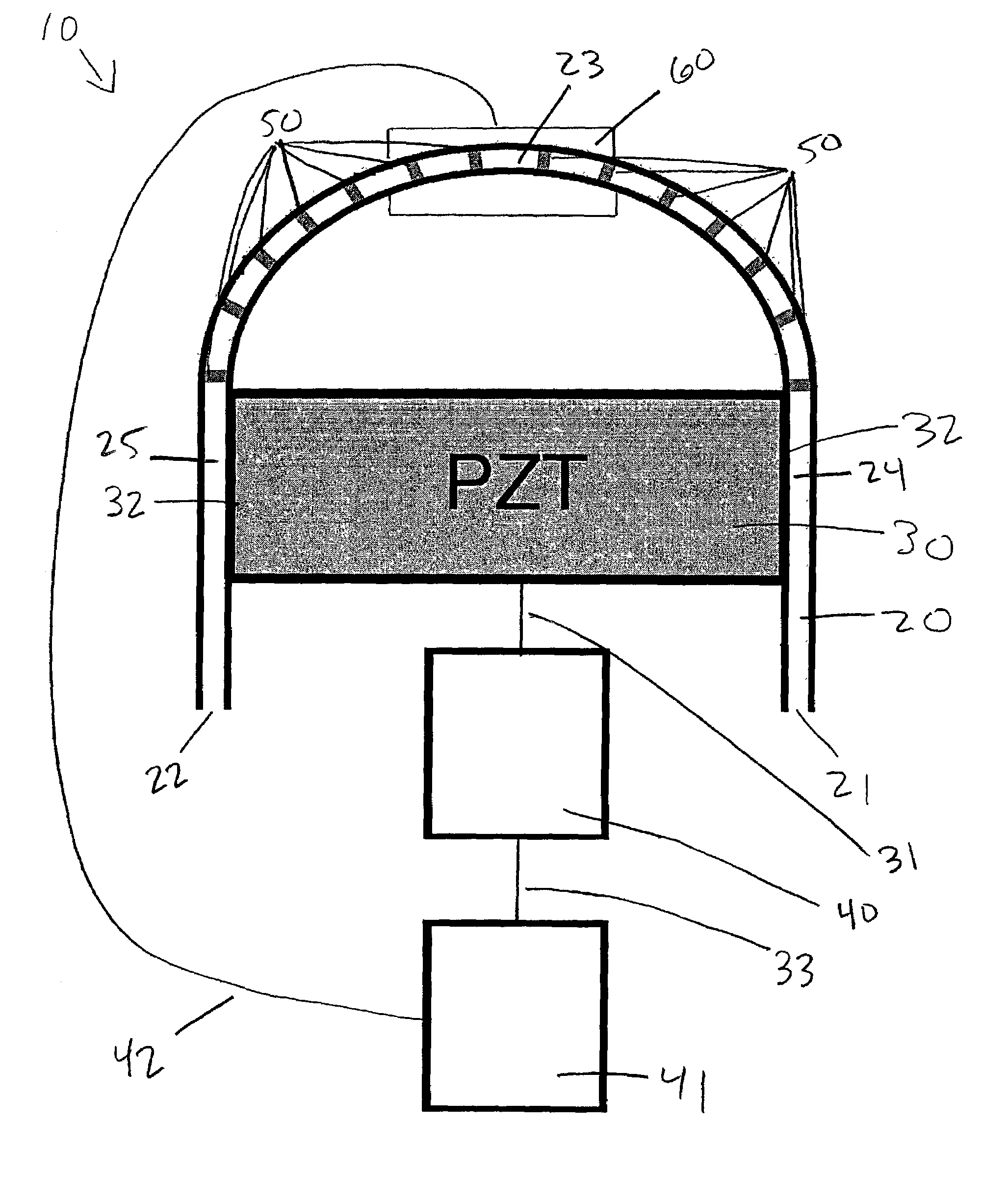
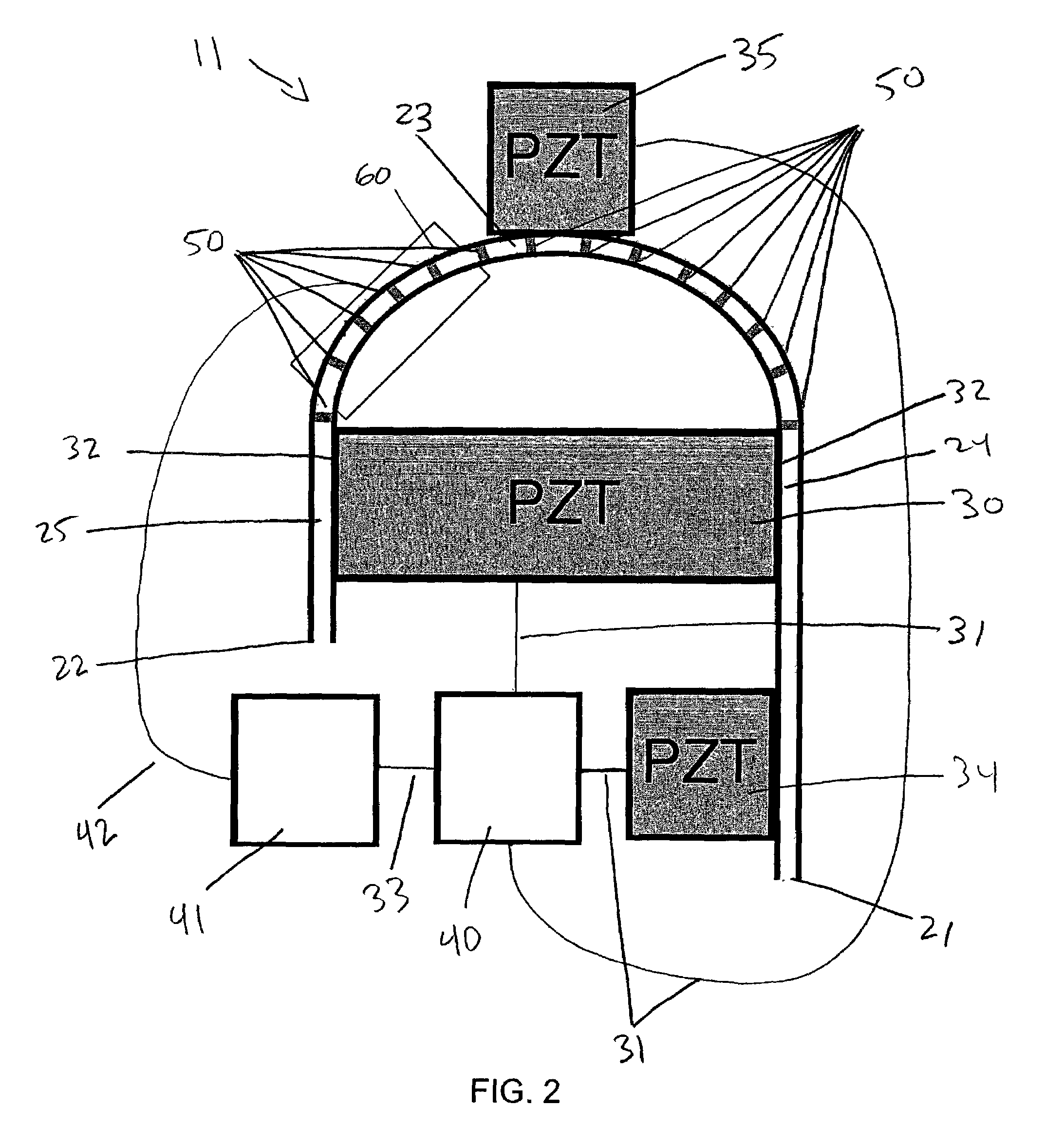
[0019]With reference to the drawings, FIG. 1 shows a preferred embodiment of an apparatus for separating particles by size in accordance with the invention indicated generally at 10. The apparatus 10 includes a vessel 20, which may be a polyimide coated glass capillary tube having an inner diameter of about 100 μm, an outer diameter of about 200 μm, and a coated polyimide thickness of about 12 μm, of the type which is available, for example, from Polymicro Technologies, LLC of Phoenix, Ariz. In the preferred embodiment shown in FIG. 1, the vessel 20 has an input end 21, an output end 22, a curved section 23, an input section 24 between the input end 21 and the curved section 23, and an output section 25 between the curved section 23 and the output end 22. The vessel preferably also bears visible markers 50, for example litho-graphically defined evenly spaced titanium thin film markers, which may be used to assist velocity measurements and to monitor bead location in the vessel, alth...


PUM

PropertyMeasurementUnit
thicknessaaaaaaaaaa
outer diameteraaaaaaaaaa

Abstract

A method and apparatus for separating a mixture of particles of various sizes in a capillary tube into groups by size using multiple forces of controlled amplitude. Ultrasonic radiation at a first selected frequency is applied to set up a standing pressure wave in the capillary tube, resulting in a first aggregating force which causes particles of all sizes to aggregate at positions within the capillary tube which correspond to nodes or anti-nodes of the standing wave. Transverse vibrations are also applied to the capillary tube. The frequency of the ultrasonic radiation is adjusted to reduce the magnitude of the first aggregating force. Inertial forces resulting from the transverse vibrations then cause the particles to separate by size. The apparatus and method allows a mixture of particles to be separated by size quickly, without requiring the use of high voltages.

Description

STATEMENT OF GOVERNMENT RIGHTS[0001]This invention was made with United States government support awarded by the following agencies: DOD ARPA F30602-00-2-0572. The United States has certain rights in this invention.FIELD OF THE INVENTION[0002]The present invention relates generally to the field of separating particles by size (particle chromatography), and particularly to separating particles by size using ultrasound.BACKGROUND OF THE INVENTION[0003]Many fluids and other materials used in science and industry, especially biological materials, contain particles having various sizes. For example, blood contains red blood cells, white blood cells, platelets, and other components which can be distinguished by their size. Further, a wide variety of biological materials, such as cells, proteins, antibodies, and DNA, can be bound to polystyrene and latex beads of various sizes. For example, antibodies immobilized on beads of various sizes are used in integrated protein bioassays, an accept...

Claims


Application Information

Patent Timeline
Patent Type & Authority Patents(United States)
IPC IPC(8): B01D43/00B01J8/16B01J19/10B03B5/00G01N15/02
CPCB01J8/16G01N15/0255B03B5/00B01J19/10
Inventor LAL, AMITLEE, CHUNG HOON
Owner WISCONSIN ALUMNI RES FOUND
Why Eureka
Try Eureka