Nitride phosphor and method for preparation thereof, and light emitting device

a phosphor and phosphor technology, applied in the field of illumination, can solve the problems of low color rendering property deficient in red, low efficiency of phosphor emitting reddish light, high color temperature, etc., and achieve excellent luminescence properties and high luminescence brightness

Inactive Publication Date: 2007-08-21
NICHIA CORP
View PDF18 Cites 130 Cited by
  • Summary
  • Abstract
  • Description
  • Claims
  • Application Information

AI Technical Summary

Benefits of technology

[0016]The first nitride phosphor containing the Group I Element consisting of Li, Na, K, Rb and Cs has a higher luminescence efficiency in comparison with a nitride phosphor not containing the Group I Element. This is considered because the above-mentioned Group I Element works as a flux during synthesis and then the Group I Element which worked as the flux exists between phosphor particles, or the luminescence itself of the phosphor is hardly inhibited because the Group I Element is scattered during its production steps. Further, the particle diameter of the nitride phosphor can be controlled by containing the Group I Element in the nitride phosphor.
[0183]There can be formed a liquid crystal display or a light source for illumination of improving the color rendering property and hardly generating the color deviation even by the change of ambient temperatures in comparison with a conventional technology, by making such a constitution.

Problems solved by technology

However, the above-mentioned white color light emitting device has defects that there is little red component in luminescence, color temperature is high, and only illumination light having low color rendering property which is deficient in red is obtained.
However, since a conventional phosphor emitting reddish light has low efficiency caused by near ultra violet to blue light excitation and low chemical and thermal stabilities, durability is not adequate, therefore it is not practically used.
Further, a conventional phosphor emitting red light has inadequate efficiency caused by near ultra violet to blue light excitation and inadequate durability, therefore it is not practically used.

Method used


Image

  • Nitride phosphor and method for preparation thereof, and light emitting device
  • Nitride phosphor and method for preparation thereof, and light emitting device
  • Nitride phosphor and method for preparation thereof, and light emitting device

Examples


examples

[0647]The phosphor and light emitting device related to the present invention are illustrated below according to Examples, but not limited to these Examples.

[0648]Further, temperature characteristic is shown by a relative brightness in which the luminescence brightness at 25° C. is 100%, in Examples below.

[0649]Further, the particle diameter is a value obtained by an air transmission method called as F.S.S.S.No. (Fisher Sub Sieve Sizer's No.).

[0650]Further, afterglow is measured by switching off the lamp of an excitation light source after irradiating light of 253.7 nm at room temperature (20° C.) for a fixed time. The basis of time is that the time of the instance of switching off the lamp of the excitation light source is defined as zero. When the brightness during irradiation of the excitation light source is set as the brightness basis of 100%, a time required for the brightness being quenched to 1 / 10 is measured. The afterglow property is determined by making the measurement re...

examples 1 to 80

[0651]The phosphors of Examples 1 to 80 are the phosphor related to the mode 1 of operation.

[0652]Table 1 shows the properties of the nitride phosphor of Examples 1 to 80 related to the present invention.

[0653]Further, FIG. 5 is a drawing showing a luminescence spectrum when the nitride phosphor of Example 60 was excited at Ex=460 nm. FIG. 6 is a drawing showing the excitation spectrum of the nitride phosphor of Example 60. FIG. 7 is a drawing showing the reflection spectrum of the nitride phosphor of Example 60.

[0654]

TABLE 1TemperatureMolecularParticleCharac-AdditionMolecularweightColorColorBright-Quantumdiam-After-teristicsEle-amountweight ofoftonetonenessefficiencyeterglow100°200°ment(ppm)addition sourceReagent makerelementxyY(%)Q(%)(μm)(msec)C.C.1Li100LiOH.H2OWako Reagent super-6.940.5850.407205.5211.82.5282Li500 41.96high grade 124-012120.5850.407196.2201.82.33095.465.53Na100Na2CO3Wako Reagent super-22.990.5840.407210.9215.92.6144Na500105.99high grade 197-015850.5850.406215.522...

example 81

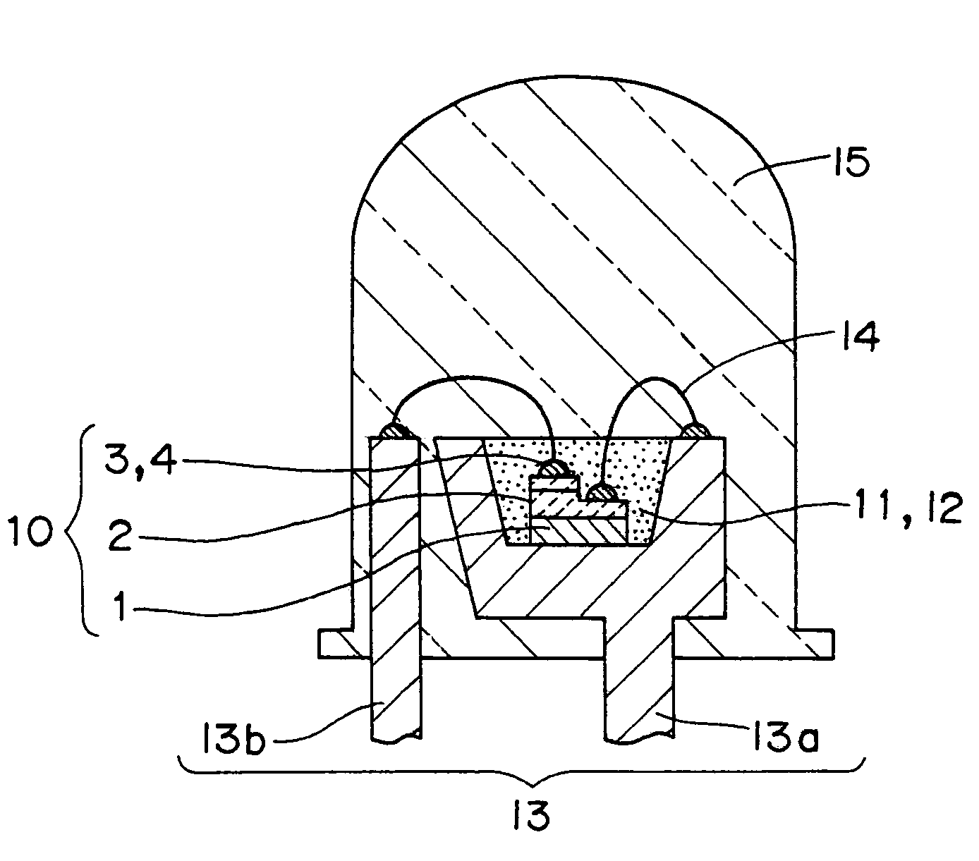
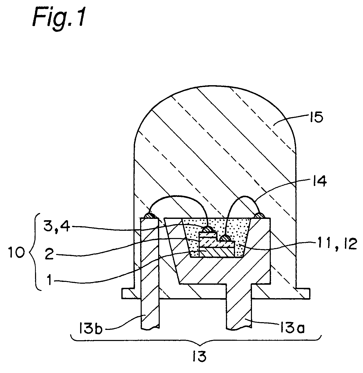
[0677]The light emitting device of Example 81 is a white light emitting device which was constituted using the phosphor of Example 15 and to which a reddish component was added. Further, the light emitting device of Example 81 is the type 1 light emitting device shown in FIG. 1. Further, FIG. 8 is a drawing showing the chromaticity coordinate of the light emitting device of Example 81.

[0678]In the light emitting element 10 of Example 81, n+GaN:Si, n-AlGaN:Si, n-GaN, GaInN QWs, p-GaN:Mg, p-AlGaN:Mg, and p-GaN:Mg are laminated in order on the sapphire substrate 1 as the semiconductor layer 2. Further, the portion of n+GaN:Si is etched and exposed to form an n-type electrode. Copper with Fe is used for the lead frame 13. The light emitting element 10 is die-bonded at about the central part of the cup bottom of the mount lead 13a. Gold is used for the electroconductive wire 14, and Ni plating is carried out on the bump 4 for electrically connecting the electrode 3 with the electroconduc...


PUM

PropertyMeasurementUnit
peak wave lengthaaaaaaaaaa
luminescence spectrumaaaaaaaaaa

Abstract

To provide a phosphor containing a comparatively much red component and having high light emitting efficiency, high brightness and further high durability, the nitride phosphor is represented by the general formula LXMYN((2 / 3)X+(4 / 3)Y):R or LXMYOZN((2 / 3)X+(4 / 3)Y−(2 / 3)Z):R (wherein L is at least one or more selected from the Group II Elements consisting of Mg, Ca, Sr, Ba and Zn, M is at least one or more selected from the Group IV Elements in which Si is essential among C, Si and Ge, and R is at least one or more selected from the rare earth elements in which Eu is essential among Y, La, Ce, Pr, Nd, Sm, Eu, Gd, Tb, Dy, Ho, Er and Lu.); contains the another elements.

Description

[0001]This application is the US national phase of international application PCT / JP03 / 03418, filed in English on 20 May 2003, which designated the US. PCT / JP03 / 03418 claims priority to JP Application No. 2002-080879 filed 22 Mar. 2002, JP Application No. 2002-126566 filed 26 Apr. 2002, JP Application No.2002-148555 filed 23 May 2002, JP Application No. 2002-167166 filed 7 Jun. 2002, JP Application No. 2002-187647 filed 27 Jun. 2002, JP Application No. 2002-226855 filed 5 Aug. 2002, JP Application No. 2002-348386 filed 29 Nov. 2002, JP Application No. 2002-348387 filed 29 Nov. 2002 and JP Application No. 2002-351634 filed 3 Dec. 2002. The entire contents of these applications are incorporated herein by reference.TECHNICAL FIELD[0002]The present invention relates to an illumination such as a light emitting device, a fluorescent lamp and the like, and relates to a display, a back light for liquid crystal and the like which is used for a semiconductor light emitting element, and specifi...

Claims


Application Information

Patent Timeline
Patent Type & Authority Patents(United States)
IPC IPC(8): C09K11/59C09K11/66C09K11/08C09K11/77H01L33/50
CPCC01B21/0602C01B21/0821C04B35/44C04B35/584C04B35/597C09K11/0883C09K11/77C09K11/7702C09K11/7703C09K11/7728C09K11/773C09K11/7731H01L33/502C01P2002/52C01P2002/84C01P2004/03C01P2004/61C04B2235/3224C04B2235/3225C04B2235/3227C04B2235/3229C04B2235/3286C04B2235/3852C04B2235/3873C04B2235/3895C04B2235/764H01L2224/48091H01L2224/49107H01L2224/48247H01L2224/48257H01L2924/01019H01L2924/01021H01L2924/01037H01L2924/01055H01L2924/01066H01L2924/01067H01L2924/01068H01L2924/01322H01L2224/45139H01L2224/45144H01L2924/12041H01L2224/32245H01L2224/48464H01L2224/73265H01L2224/8592H01L2924/3025H01L2224/48465H01L2924/00014H01L2924/00H01L2224/45015H01L2924/181H01L2224/45124H01L2224/45147H01L2224/45169Y02B20/00H01L2924/20751H01L2924/20752H01L2924/20753H01L2924/20754H01L2924/00012H01L2924/01049C09K11/59
Inventor TAMAKI, HIROTOKAMESHIMA, MASATOSHITAKASHIMA, SUGURU
Owner NICHIA CORP
Why Eureka
Try Eureka