Flow-through cryogenic NMR probe

a probe and cryogenic technology, applied in the field of nmr, can solve the problems of cross-contamination between samples and transfer capability

Inactive Publication Date: 2005-01-04
BRUKER BIOSPIN
View PDF11 Cites 36 Cited by
  • Summary
  • Abstract
  • Description
  • Claims
  • Application Information

AI Technical Summary

Benefits of technology

In yet another embodiment, the probe may include a reference cell adjacent to the sample cell within which is located a reference material that is also detectable by the RF coil. In one arrangement, the reference cell surrounds the sample cell and is

Problems solved by technology

Obviously, however, although the coil is in a cryogenic environment, the liquid sample is not.
Although an RF coil surrounding the sample cell is at cryogenic temperatures, it is located in a vacuum that acts as a thermally insula

Method used


Image

  • Flow-through cryogenic NMR probe
  • Flow-through cryogenic NMR probe
  • Flow-through cryogenic NMR probe

Examples


Embodiment Construction

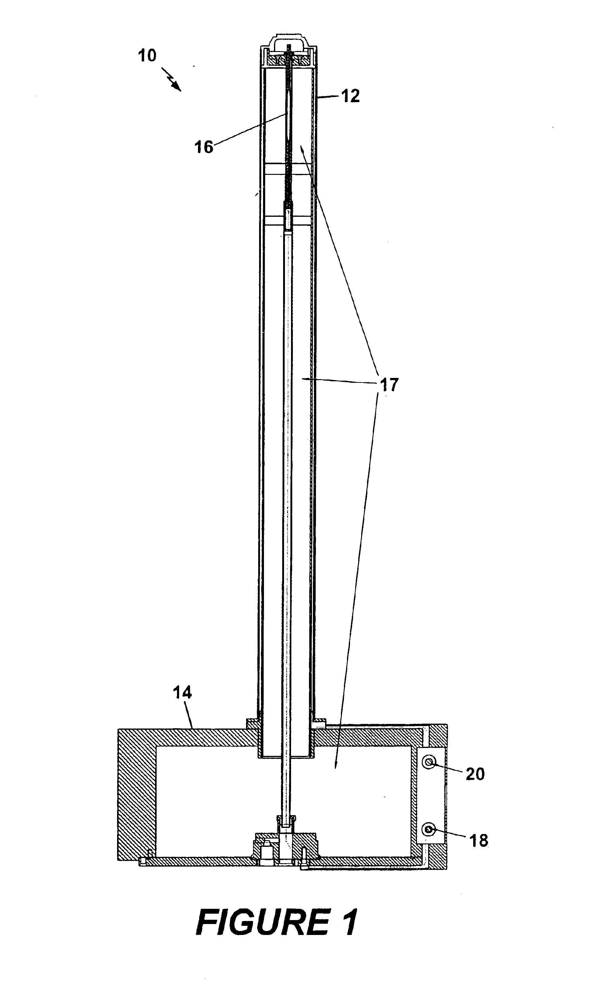
Shown in FIG. 1 is a cryogenic flow-through NMR probe 10 according to the present invention. The probe 10 has an outer casing 12 mounted to a base 14. Within the probe is a sample cell 16, which is surrounded by an NMR coil (not shown). The coil resides in one of the evacuated portions 17 of the probe, and is kept at a cold temperature via thermal conduction from a heat exchanger. The sample cell 16 is fed by a capillary that runs along a longitudinal axis of the probe, providing a flow of liquid sample solution to the sample cell from an inlet port 18. A similar capillary tube functions as a return, running from the top of the sample cell along the outer casing 12 to the base 14, and finally out outlet port 20.

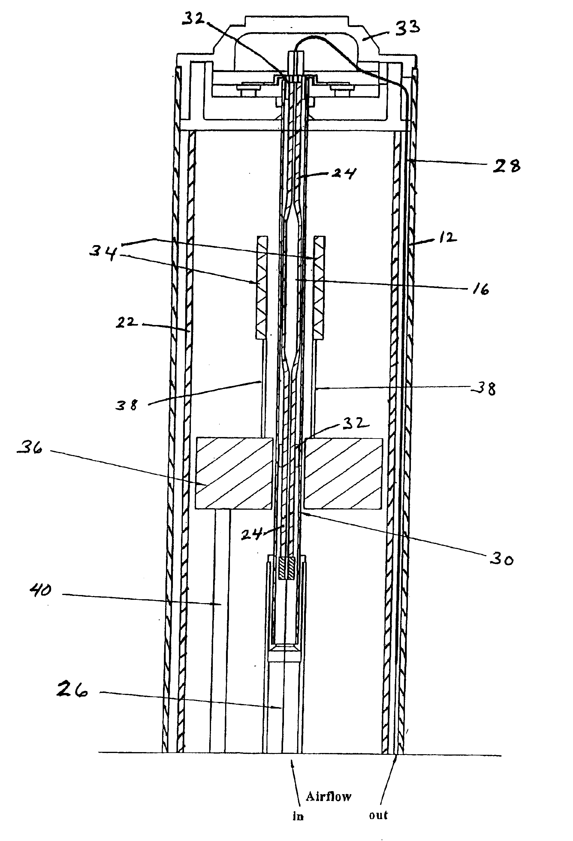
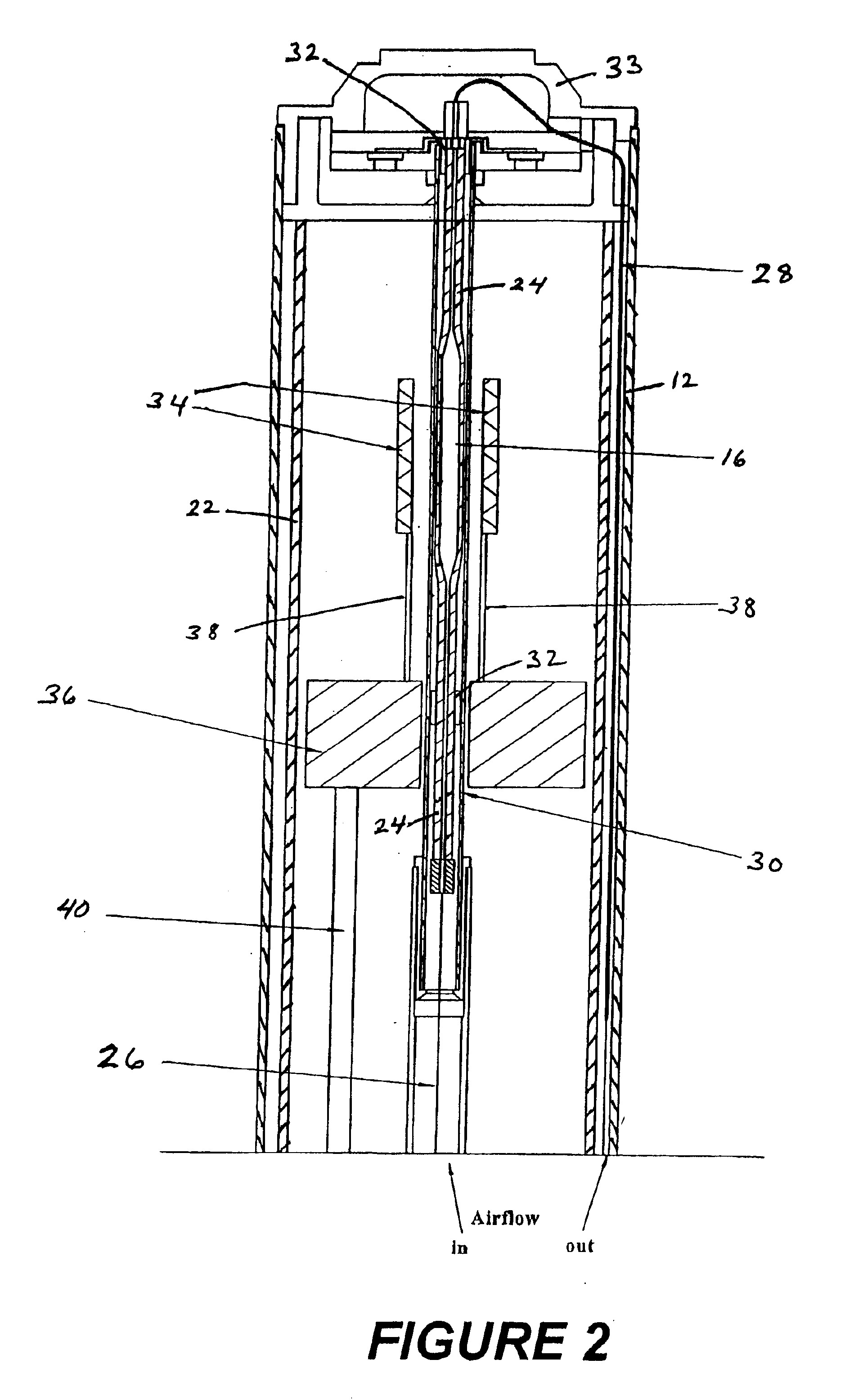
The sample region of the probe is shown in more detail in FIG. 2. The outer casing 12, preferably cylindrical, may be constructed from a non-magnetic metal. Also constructed from a similar material is an inner casing 22. The inner casing is preferably also cylindrical, and se...


PUM


Abstract

A nuclear magnetic resonance (NMR) spectroscopy probe has a sample cell into and out of which a room temperature liquid sample may be directed. The cell is surrounded by a radio frequency coil that is used to perform NMR measurements of the liquid sample, and which is maintained at cryogenic temperatures. The coil is separated from the sample cell by a thermally insulative boundary, such as a vacuum. The sample may enter the cell through an input path, and may exit through an output path. The input path, output path and sample cell may be surrounded by a sheath through which flows room temperature gas. The ends of the sample cell may be tapered to promote thorough flow through the cell, and flow diverters may be included in the sample cell adjacent to the input and output paths to force flow to the outer wall of the sample cell.

Description

FIELD OF THE INVENTIONThis invention relates generally to the field of nuclear magnetic resonance (NMR) and, more particularly, to NMR using cryogenically-cooled probes.BACKGROUND OF THE INVENTIONIn an NMR spectrometer, a sample is placed in a static magnetic field which causes atomic nuclei within the sample to align in the direction of the field. Transmit and receive coils, which may be combined in a single coil or set of coils, are placed in the probe positioned close to the sample. The transmit coils apply an RF magnetic field orthogonal to the direction of the static magnetic field, perturbing the alignment of the nuclei. The transmit signal is then turned off, and the resonant RF signal of the sample is detected by the receiver coil. The sensitivity of the spectrometer depends on a number of factors, including the strength of the static field, the closeness of the coupling between the RF coils and the sample, and the resistance of the RF coil.Currently, most commercial NMR spe...

Claims


Application Information

Patent Timeline
IPC IPC(8): G01R33/30G01R33/34
CPCG01R33/307G01R33/34092G01R33/34023
Inventor HOFMANN, MARTINSPRAUL, MANFREDNAST, ROBERT ERICHARRIS, DAMON LESLIE
Owner BRUKER BIOSPIN
Why Eureka
Try Eureka