Bus total overcurrent system for a protective relay

a relay and total overcurrent technology, applied in circuit arrangements, emergency protective circuit arrangements, electrical equipment, etc., can solve problems such as delay in the high-speed tripping process, high cost, and high cos

Inactive Publication Date: 2005-01-04
SCHWEITZER ENGINEERING LABORATORIES
View PDF11 Cites 32 Cited by
  • Summary
  • Abstract
  • Description
  • Claims
  • Application Information

AI Technical Summary

Problems solved by technology

The traditional BTOS application has certain disadvantages; for instance, it is undesirable that the BTOS arrangement provides high-speed tripping in response to transformer low-voltage side faults.
Tripping by the BTOS time overcurrent element will also typically delay the high speed tripping process, although this is frequently resolved by using a high set overcurrent element.
Further, in those situations where the strength of the source 10 changes significantly over time, security can be compromised if there are no compensating elements.
Hence, there are disadvantages and limitations of existing BTOS arrangements.

Method used


Image

  • Bus total overcurrent system for a protective relay
  • Bus total overcurrent system for a protective relay
  • Bus total overcurrent system for a protective relay

Examples


Embodiment Construction

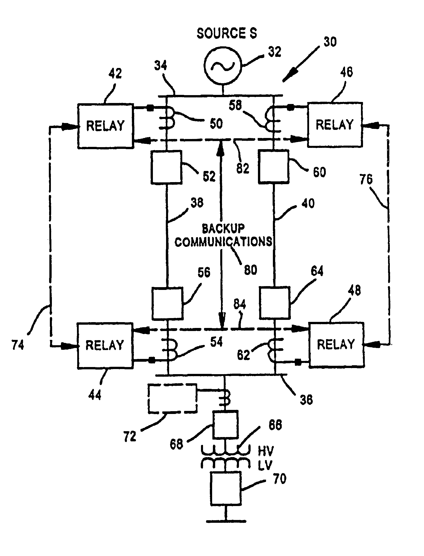
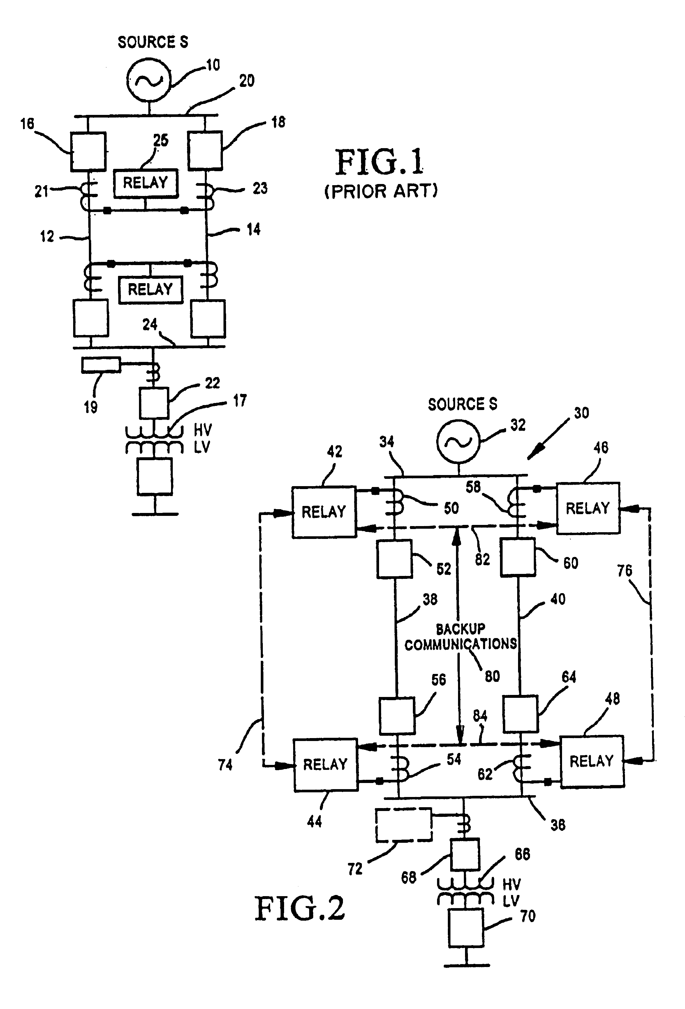
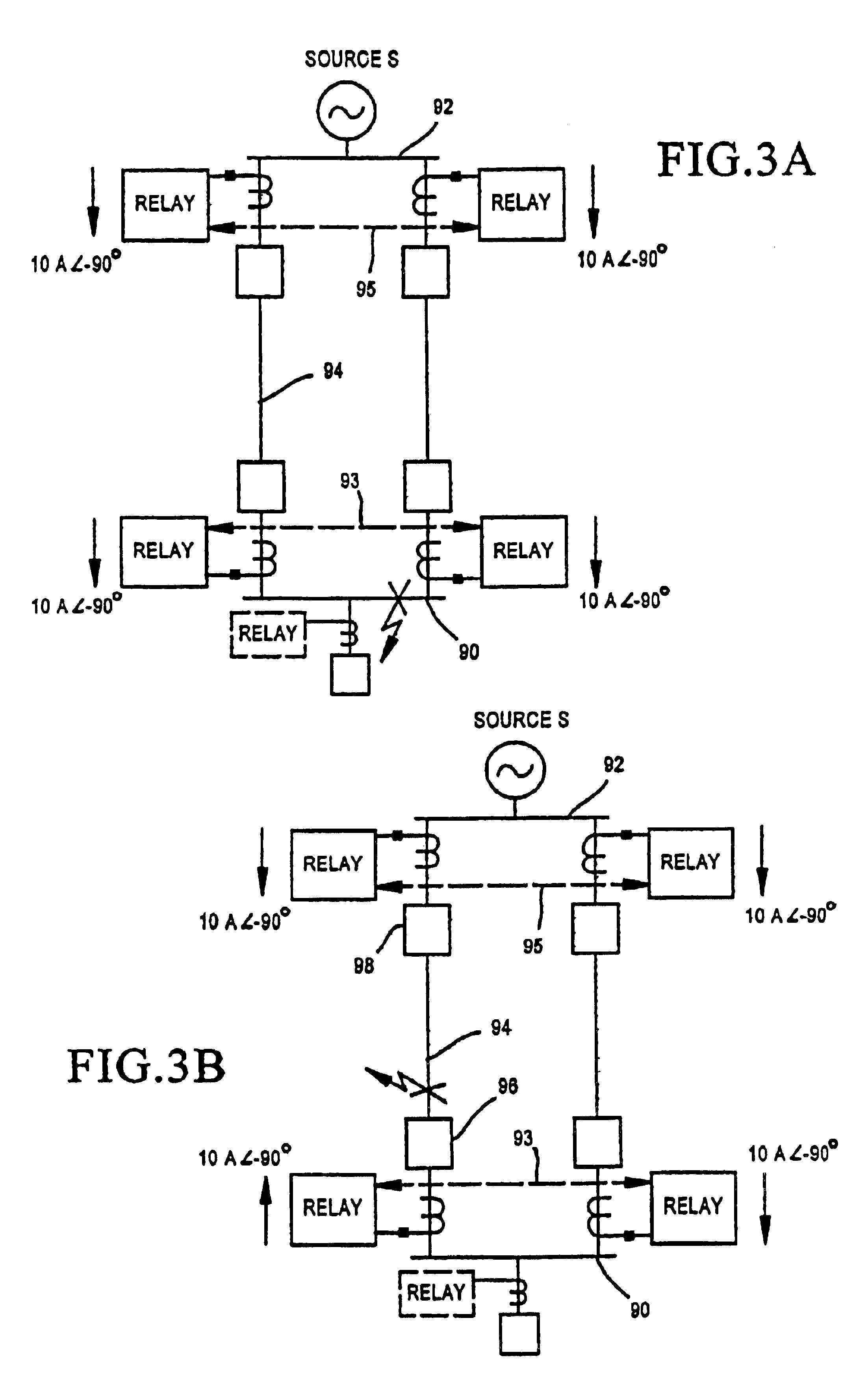
Referring now to FIG. 2, a bus total overcurrent system (BTOS) of the present invention is shown. The system of FIG. 2, shown generally at 30, includes a source 32 for buses 34 and 36, with feeder lines 38 and 40 extending between them. Line 38 has relays 42 and 44 associated therewith at opposing ends of the line. Line 40 has relays 46 and 48 associated therewith at opposing ends of that line. Relay 42 is provided current values from power line 38 through current transformer (CT) 50 with circuit breaker 52 associated therewith. Relay 44 has current values provided by CT 54, with circuit breaker 56 associated therewith. Relay 46 has current values provided by CT 58, with circuit breaker 60 associated therewith, while relay 48 has current values provided by CT 62, with and circuit breaker 64 associated therewith.

Transformer 66 is connected to bus 36 with circuit breakers 68 and 70 positioned on the high-voltage side and low-voltage side, respectively, of the transformer, with relay 7...


PUM


Abstract

A power system bus total overcurrent system is used with a part of a power system which includes two buses and first and second power line portions which extend between them. A protective relay system includes protective relays for each of the first and second power line portions, located near the two buses, wherein the relays determine the total current into and out of each bus. The bus total overcurrent system includes first and second communication lines between each pair of relays and another communication line which extends between the first and second communication lines. In a current balance arrangement, the relays measure difference current using the same communication line arrangement between the two pairs of relays to determine a fault condition. Fault determinations are made in each case by the protection algorithms from total and difference currents.

Description

TECHNICAL FIELDThis invention relates generally to overcurrent elements in a protective relaying system for detecting overcurrent conditions on a power system, and more specifically concerns a power line bus total overcurrent relay for determining total overcurrent on a bus.BACKGROUND OF THE INVENTIONA bus is a portion of an electric power system from which individual feeder lines extend to individual users. Typically, the bus will include three-phase current values and IA, IB, IC and three phase voltage values VA, VB and VC. Many electric power protection applications include a bus total overcurrent system (BTOS), which measures all of the current entering and leaving a protected bus. The vector sum of the currents flowing through the circuit breakers connected to the bus is useful as an input to a time overcurrent element in a protective relay.FIG. 1 shows a typical BTOS arrangement involving two feeder lines. With an electromechanical or other static relay, the three-phase curren...

Claims


Application Information

Patent Timeline
Patent Type & Authority Patents(United States)
IPC IPC(8): H02H7/22H02H7/00
CPCH02H7/22
Inventor ROBERTS, JEFFREY B.WHITEHEAD, DAVID E.
Owner SCHWEITZER ENGINEERING LABORATORIES
Why Eureka
Try Eureka