Digital protective relay

一种保护继电器、数字的技术,应用在紧急保护电路装置、校准/查找保护装置、印刷电路等方向,能够解决接地效率降低等问题

Active Publication Date: 2013-10-23
LSIS CO LTD
View PDF3 Cites 2 Cited by
  • Summary
  • Abstract
  • Description
  • Claims
  • Application Information

AI Technical Summary

Problems solved by technology

However, such a conventional grounding method has a problem that the housing of the digital protection relay should be formed of a metal conductor
However, the problem with such a method is that the grounding efficiency is reduced

Method used


Image

  • Digital protective relay
  • Digital protective relay
  • Digital protective relay

Examples


Embodiment Construction

[0025] Exemplary embodiments will now be described in detail with reference to the accompanying drawings. In order to simplify the description with reference to these drawings, the same or equivalent components will have the same reference numerals, and a description thereof will not be repeated.

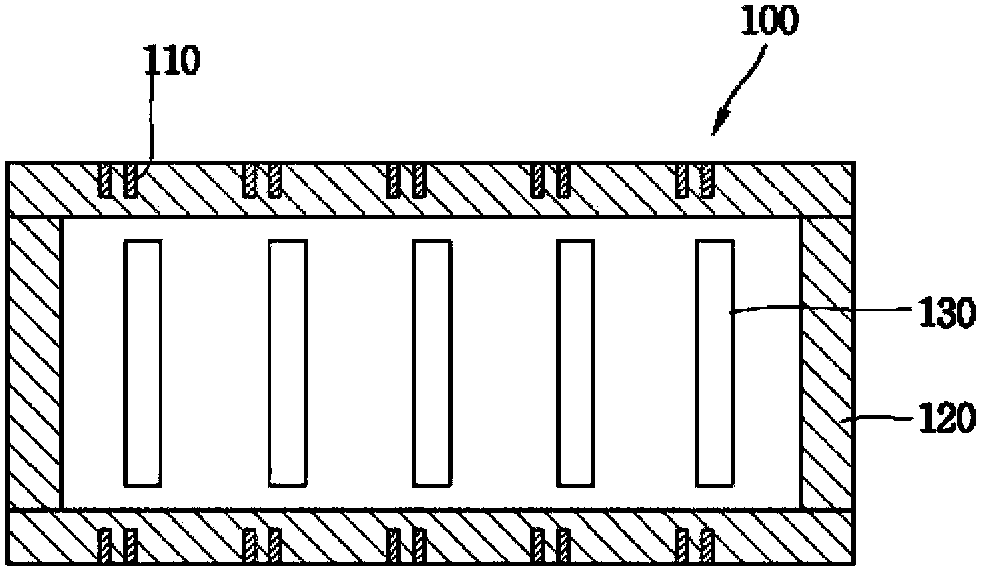
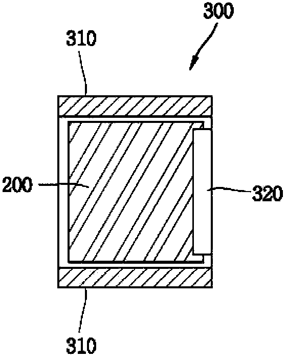
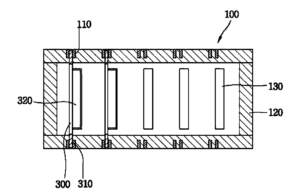
[0026] refer to Figure 1 to Figure 3 , according to the present invention, the digital protection relay includes a backplane printed circuit board (hereinafter, the printed circuit board is abbreviated as PCB) 100 , and a sub PCB 300 .

[0027] PCB 100 refers to a large shared circuit board that performs the function of a motherboard. And the sub PCB 300 refers to a small subsidiary circuit board that performs its own function and is plugged into the backplane PCB 100 .

[0028] In terms of quantity, at least 1 (for example, 5) sub PCBs 300 can be provided.

[0029] refer to figure 2 , the sub PCB includes the electronic circuit 200 for performing its own function, and the ele...


PUM


Abstract

A digital protective relay includes at least one daughter PCB (300) having an electronic circuit which generates electromagnetic interference noise or high frequency noise; and a backplane printed circuit board (100) having, on an upper surface thereof, a plurality of first connectors (130) for connection with the daughter PCB (300), the backplane PCB (100) being connected to the daughter PCB through the first connectors (130), and providing a noise discharge path (120) along which the electromagnetic interference noise or the high frequency noise from the daughter PCB flows to an external ground.

Description

technical field [0001] The present disclosure relates to digital protective relays, and more particularly, to the grounding arrangement of a printed circuit board of a digital protective relay. Background technique [0002] The digital protection relay refers to a relay used to prevent the spread of an electrical accident by operating a circuit breaker upon detection of a fault current in an electric power system. For example, if an electrical accident occurs in a circuit, such as a short circuit or an eddy current, the digital protection relay can control a circuit breaker to disconnect the circuit where the accident has occurred, so as not to spread the electrical accident. [0003] In conventional technology, the printed circuit board (PCB) is grounded by installing pin contacts that can contact the housing at the track of the printed circuit board (PCB). However, such a conventional grounding method has a problem in that the case of the digital protective relay should b...

Claims


Application Information

Patent Timeline
Patent Type & Authority Applications(China)
IPC IPC(8): H05K1/14
CPCH05K1/141H02H7/20H05K1/0218H05K2201/10295H05K1/0215H05K2201/044H05K3/366H01H69/01
Inventor 安洪善
Owner LSIS CO LTD
Why Eureka
Try Eureka