
Primary cut-out state monitoring method

A high-voltage circuit breaker, state technology, applied in circuit breaker testing, circuit devices, emergency protection circuit devices, etc., can solve the problems of low efficiency and high monitoring costs, and achieve good economic results

Inactive Publication Date: 2008-04-23
苏盛 +2
View PDF2 Cites 1 Cited by
  • Summary
  • Abstract
  • Description
  • Claims
  • Application Information

AI Technical Summary

Problems solved by technology

[0005] The purpose of the present invention is to provide a simple and economical high-voltage circuit breaker state monitoring method that can effectively reflect the state of each component of the high-voltage circuit breaker, so as to overcome the problems of high cost and low efficiency of existing high-voltage circuit breaker monitoring

Method used


Image

  • Primary cut-out state monitoring method
  • Primary cut-out state monitoring method
  • Primary cut-out state monitoring method

Examples


Embodiment Construction

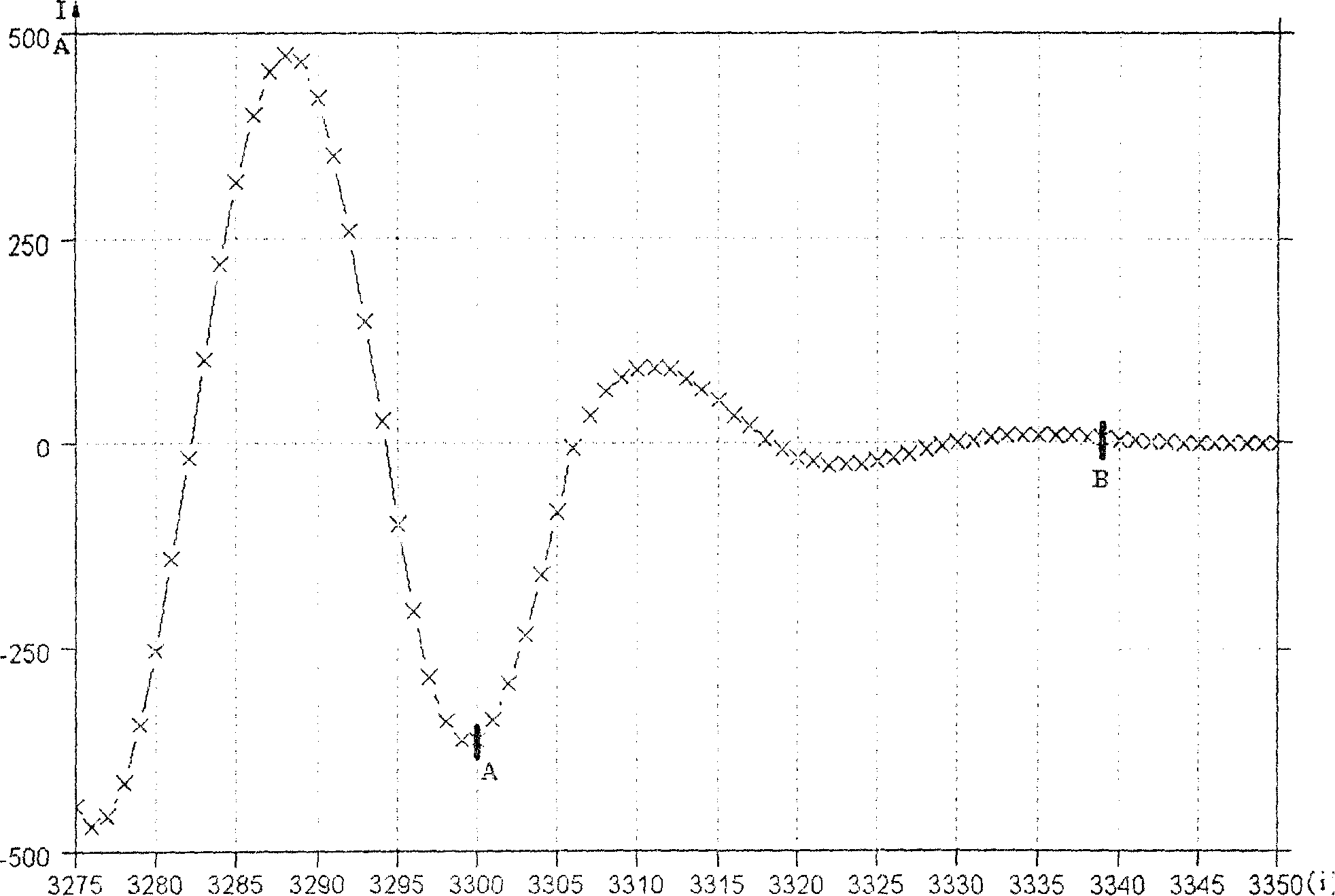
[0022] see figure 1 , figure 1 Schematic diagram of the composition of the fault isolation time of a high-voltage circuit breaker. where: t g Is the fault isolation time, the fault isolation time starts from the time when the fault occurs, and ends at the moment when the effective value of the arc current decays to 5% of the current effective value at the moment of opening; t b is the protection time, which is from the time when the fault occurs to the time when the protection outputs the trip signal through the pressure plate; t k It is the breaking time, which is the time between when the circuit breaker gets the trip action signal (that is, the moment when the protection outputs the trip signal through the pressure plate) to the effective value of the arc current decays to 5% of the effective value of the current at the moment of opening; t f is the opening time, which is the time from when the circuit breaker receives the tripping action signal to when the circuit break...


PUM


Abstract

The invention discloses a primary cut-out state monitoring method, which comprises following steps: using existing fault recording apparatus and digital protective-relay device in converting station automatic system to record normal divided brake current decay process; using recorded data to calculate circuit breaker opening time; then estimating circuit breaker state according to opening time of circuit breaker and opening time trend in some time.

Description

technical field [0001] The invention relates to a method for monitoring power equipment, in particular to a method for monitoring the state of a high-voltage circuit breaker. Background technique [0002] High-voltage circuit breakers are high-voltage electrical equipment used to close and break normal circuits, fault circuits, or to isolate power supplies and achieve safe grounding. As an important control and protection device of the power system, high-voltage circuit breakers play an important role in the safe and reliable operation of the power system. The power system must carry out regular maintenance, but the current regular maintenance system has obvious defects. On the one hand, overhauling equipment that is in good operating condition may destroy the original good condition; secondly, blindly overhauling equipment regardless of equipment status causes a lot of waste of manpower and material resources; It is not uncommon for power equipment to pass the pre-test bu...

Claims


Application Information

Patent Timeline
Patent Type & Authority Patents(China)
IPC IPC(8): G01R31/327G01R31/333H02H3/05
Inventor 苏盛陈伟乐李继洸曾祥君段献忠
Owner 苏盛
Learn More