Protective relay system and protective relay device

A relay device and relay system technology, which is applied in the direction of emergency protection circuit devices, circuit devices, emergency protection devices with automatic disconnection, etc., can solve the problems of synchronization accuracy reduction, synchronization frame transmission time delay, misoperation, etc.

Inactive Publication Date: 2015-09-16
KK TOSHIBA
View PDF7 Cites 2 Cited by
  • Summary
  • Abstract
  • Description
  • Claims
  • Application Information

AI Technical Summary

Problems solved by technology

[0005] If the transmission time of the synchronization frame is delayed, there will be a difference between the transmission time of the outgoing path and the transmission time of the return path between protective relay devices, and the synchronization accuracy will decrease
If the synchronization accuracy is lowered, differential calculations are performed at different sampling timings in the current differential relay device, so malfunctions may occur

Method used


Image

  • Protective relay system and protective relay device
  • Protective relay system and protective relay device
  • Protective relay system and protective relay device

Examples


no. 1 Embodiment approach

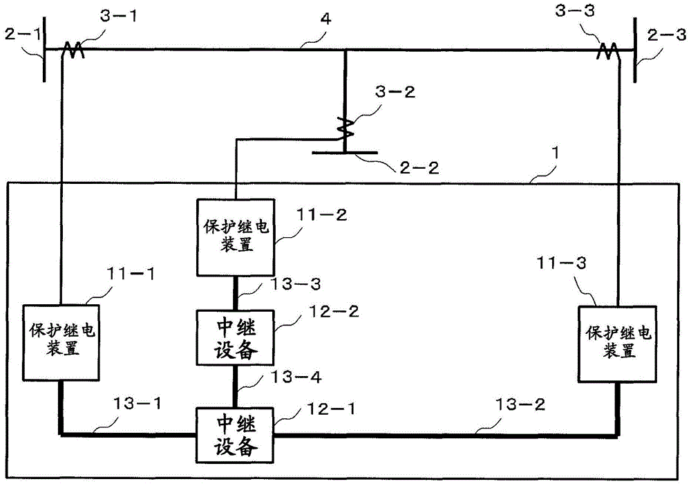
[0021] use figure 1 , and the configuration of the protective relay system according to the first embodiment of the present invention will be described. figure 1 It is a block diagram showing a protective relay system for protecting a power transmission line with three terminals.

[0022] The protective relay system 1 includes protective relay devices 11-1 to 11-3, relay devices 12-1 to 12-2, and networks 13-1 to 13-4.

[0023] The protective relay devices 11-1 to 11-3 are respectively connected to the current transformers 3-1 to 3-3 provided in the vicinity of the terminals 2-1 to 2-3, and acquire electric quantity data. In addition, the protective relay devices 11-1 to 11-3 communicate via the networks 13-1 to 13-4 and the relay devices 12-1 to 12-2, respectively, and transmit and receive data frames. Here, the data frame transmitted and received between the protection relay devices 11-1 to 11-3 is an electric quantity frame including the electric quantity data obtained by...

no. 2 Embodiment approach

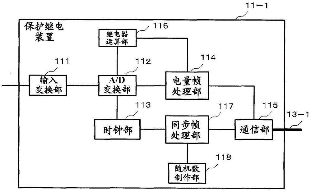
[0048] use Figure 5 , and the protective relay device according to the second embodiment will be described. The same reference numerals are assigned to the same configurations as those of the first embodiment, and description thereof will be omitted. The difference from the first embodiment is that a storage unit 119 is provided instead of the random number creation unit 118 , and a synchronous frame processing unit 117 - 1 is provided instead of the synchronous frame processing unit 117 .

[0049] The synchronization frame processing unit 117-1 transmits a synchronization frame to the protection relay devices 11-2 and 11-3 via the communication unit 115 and the network 13-1. Here, the timing (Tc) at which the synchronization frame is transmitted is within a fluctuation allowable time (Tb) after a constant time (Ta) from the sampling timing.

[0050] Within this fluctuation allowable time (Tb), transmission is performed at a timing at which an addition time (Δt) is added fr...

no. 3 Embodiment approach

[0063] use Figure 7 , and the configuration of the protective relay system according to the third embodiment of the present invention will be described. Figure 7 It is a block diagram showing a protective relay system for protecting a power transmission line with three terminals.

[0064] The protective relay system 1 includes protective relay devices 11-1 to 11-3, relay devices 12-1 to 12-2, and networks 13-1 to 13-4.

[0065] The protective relay devices 11-1 to 11-3 are respectively connected to the current transformers 3-1 to 3-3 provided in the vicinity of the terminals 2-1 to 2-3, and acquire electric quantity data. In addition, the protective relay devices 11-1 to 11-3 communicate via the networks 13-1 to 13-4 and the relay devices 12-1 to 12-2, respectively, and transmit and receive data frames. Here, the data frame transmitted and received between the protection relay devices 11-1 to 11-3 is an electric quantity frame including the electric quantity data obtained ...


PUM


Abstract

The purpose of the embodiment according to the present invention is to provide a protective relay system, a protective relay device, and a time synchronization method such that highly-accurate time synchronization between devices can be achieved. The embodiment according to the present invention relates to a protective relay system having a plurality of protective relay devices which protect a power grid on the basis of data pertaining to the amount of electricity in the power grid, said protective relay devices communicating with each other over a network. Each protective relay device comprises: a clock generation unit for periodically indicating the timing for sampling data pertaining to the amount of electricity in the power grid; a relay calculation unit for performing relay calculation on the basis of the sampled electricity amount data, and the electricity amount data received through the network; a random number generation unit for generating random numbers; and a synchronization frame processing unit for determining the timing for transmitting a synchronization frame to other protective relay devices over the network on the basis of the random number generated by the random number generation unit.

Description

technical field [0001] Embodiments of the present invention relate to a protective relay system and a protective relay device. Background technique [0002] Conventionally, protective relay systems have been used to protect power system equipment by detecting and eliminating accidents occurring in power system equipment such as transmission lines, bus bars, and transformers constituting the power system. For example, in a protection relay system for protecting power transmission lines, there is a technology in which protection relays are provided at the section ends of the power system, and the protection relays are connected by transmission lines, and accidents are detected based on the power information at each terminal. [0003] Even among protective relay devices, a current differential relay device that protects a transmission line acquires current value information at its own terminal, and transmits the current value information to a counterpart terminal via a transmis...

Claims


Application Information

Patent Timeline
Patent Type & Authority Applications(China)
IPC IPC(8): H02H3/28H02H3/02
CPCH02H7/261H02H3/28
Inventor 河原田明森贵弘犬饲道彦杉浦秀昌西田知敬
Owner KK TOSHIBA
Why Eureka
Try Eureka