

Chair having rigid structure
a chair and rigid technology, applied in the field of chairs, can solve the problems of increasing transportation costs, increasing time of assembly, and complicated working and mounting procedures
- Summary
- Abstract
- Description
- Claims
- Application Information
AI Technical Summary
Benefits of technology
Problems solved by technology
Method used
Image

Examples
Embodiment Construction
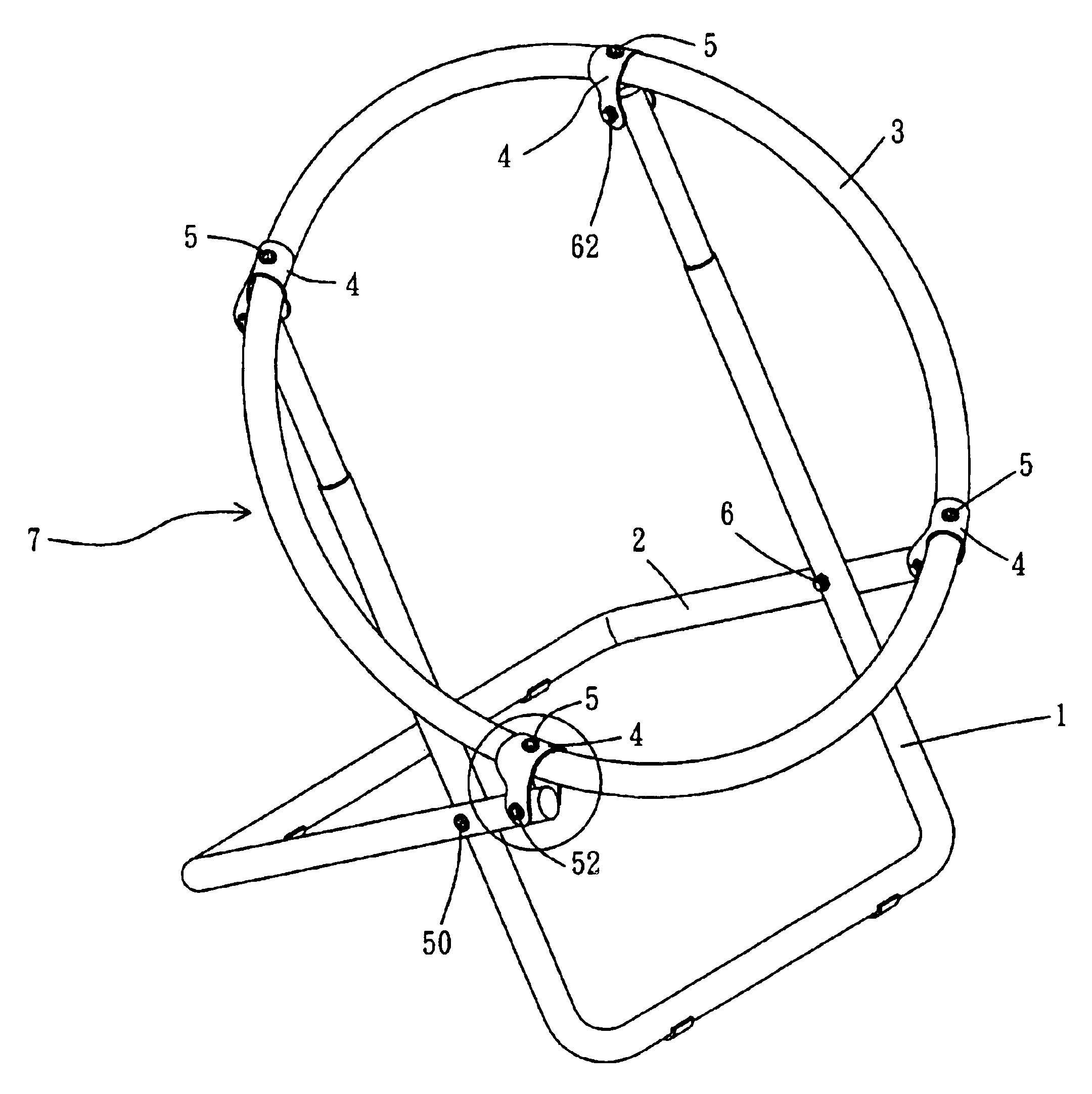
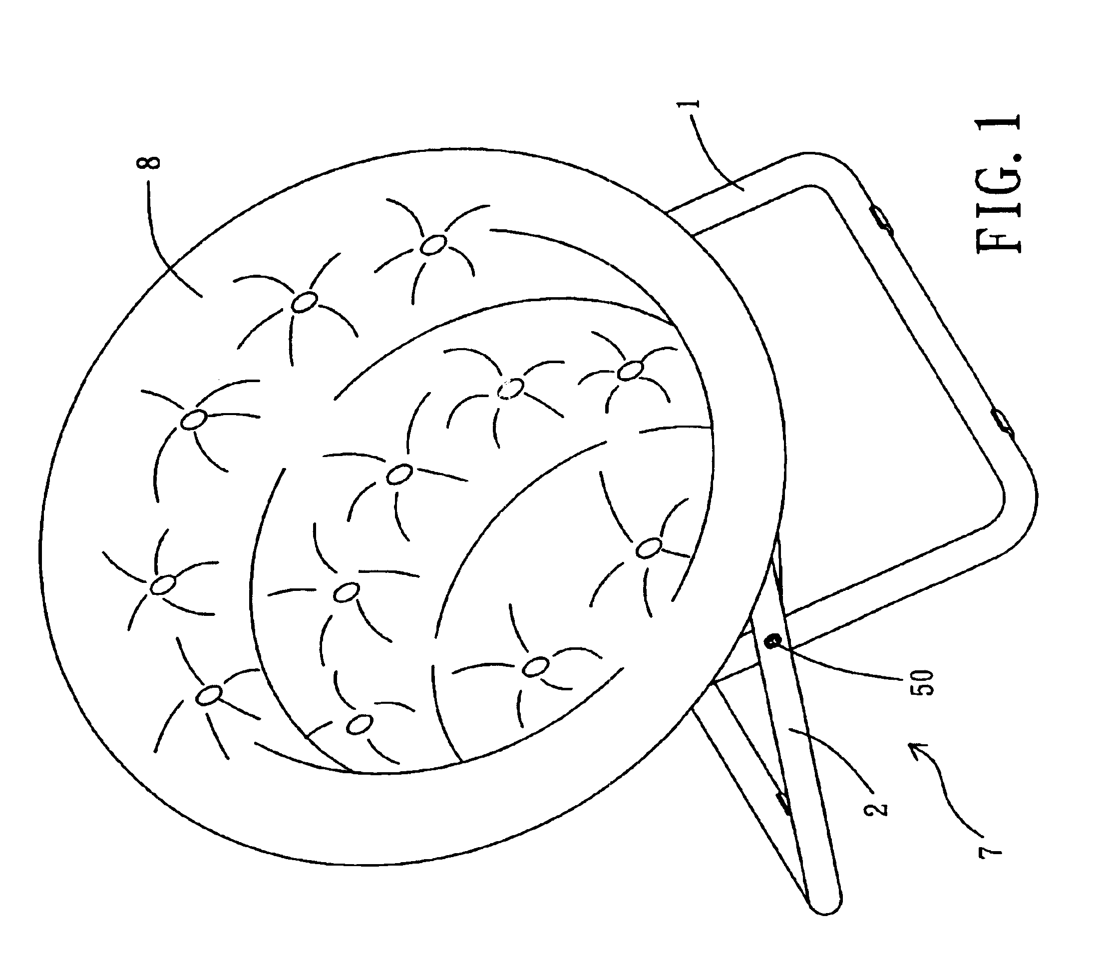
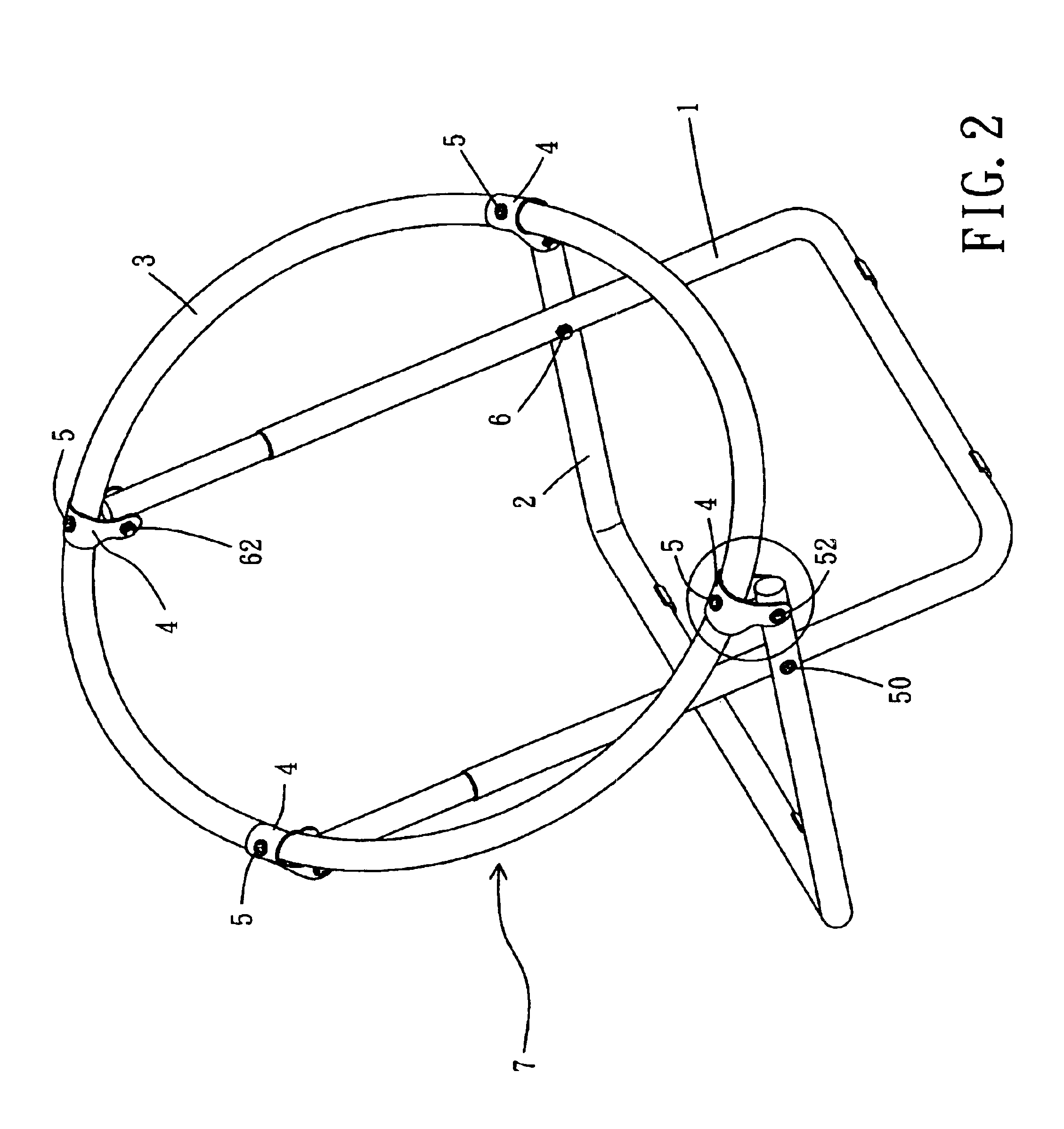
Referring to the drawings and initially to FIGS. 1-3, a chair 7 in accordance with the preferred embodiment of the present invention comprises a substantially U-shaped first leg 1, a substantially U-shaped second leg 2 pivotally mounted on the first leg 1 by two screw members 50 and two nuts 60, a circular seat frame 3 mounted on the first leg 1 and the second leg 2 by a plurality of substantially inverted U-shaped connecting members 4, and a seat cushion 8 mounted on the seat frame 3.
Referring to FIGS. 1-4, each of the connecting members 4 has an inside formed with an opening 42 facing downward for mounting the first leg 1 or the second leg 2 and has a mediate portion formed with a through hole 41 communicating with the opening 42. The seat frame 3 has a periphery formed with a plurality of screw bores 31 each aligning with the through hole 41 of a respective one of the connecting members 4. The chair 7 further comprises a plurality of locking screws 5 each extended through the thr...
PUM
 Abstract
Description
Claims
Application Information