Segmented bearing retainer

a bearing retainer and bearing cage technology, applied in the direction of rotary bearings, shafts and bearings, rolling contact bearings, etc., can solve the problems of affecting the service life of the bearing, so as to achieve the effect of convenient rotation

Active Publication Date: 2015-05-26
THE TIMKEN CO
View PDF49 Cites 8 Cited by
  • Summary
  • Abstract
  • Description
  • Claims
  • Application Information

AI Technical Summary

Benefits of technology

[0015]The rings are initially open ended to allow for assembly of the bridge segments and spacers onto the rings. The free ends of the rings have a feature which facilitates subsequently joining the ends together as part of the final assembly. In one embodiment the rings have a groove near each end which allows the rings to be connected by a joining spacer, using a crimp joint. In another embodiment the free ends of the rings are threaded with opposite handed threads and a joining spacer in the form of a turnbuckle is used to join the ends of the rings together. This embodiment allows the spacers and bridge segments to be drawn together to a desired degree of force. By drawing the spacers and bridge elements tightly together a more rigid cage structure is obtained. In another embodiment one end of the ring has a groove formed in it to receive a crimp connection and the other end of the ring is threaded. In this embodiment, the common right handed threads only may be used and the need to use the less common left handed threads is eliminated. The joining spacer in this case has threads on only one side and is crimped on the other end.

Problems solved by technology

While pin style cages provide excellent retention, they are heavy, complex, and costly to assemble.
Furthermore, some pin style cage designs can partially block flow of lubricants (especially grease) to critical wear surfaces.
They also cannot be disassembled without damaging either the cage rings or the cage pins.
The resulting cost of bearing cages produced using combinations of these various processes are unacceptably high, especially for the larger bearing sizes.
While these cages have a demonstrated ability to perform satisfactorily, there are potential limitations in scaling up this design for larger bearings containing heavy rollers.
Current polymer cages for very large bearings are made from polyether ether ketone (PEEK), an organic polymer thermoplastic which is relatively expensive.
The greater amount of PEEK required to make a sufficiently strong cage can therefore often be cost prohibitive.

Method used


Image

  • Segmented bearing retainer
  • Segmented bearing retainer
  • Segmented bearing retainer

Examples


Embodiment Construction

[0031]The following detailed description illustrates the invention by way of example and not by way of limitation. The description enables one skilled in the art to make and use the present disclosure, and describes several embodiments, adaptations, variations, alternatives, and uses of the present disclosure, including what is presently believed to be the best mode of carrying out the present disclosure.

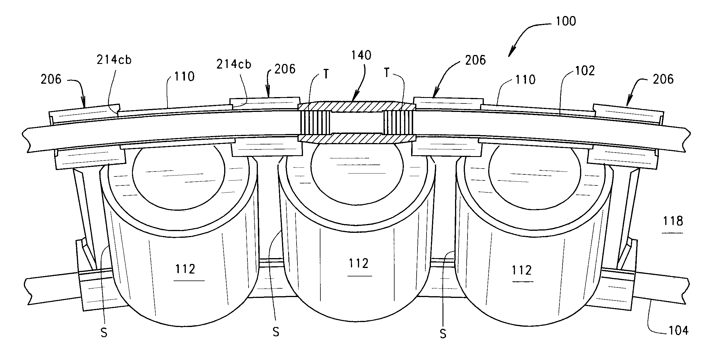
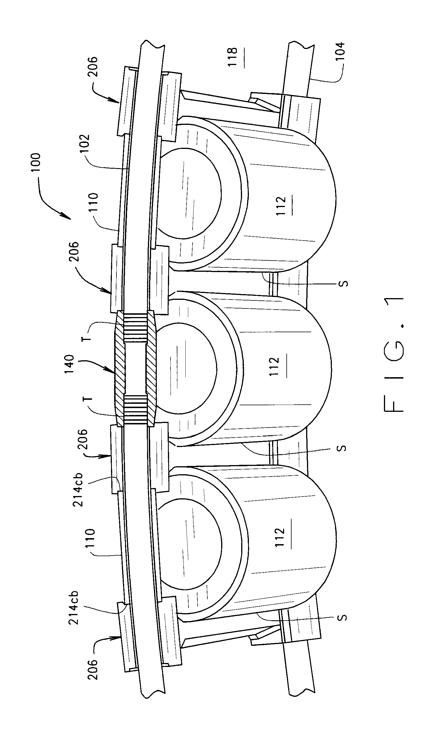
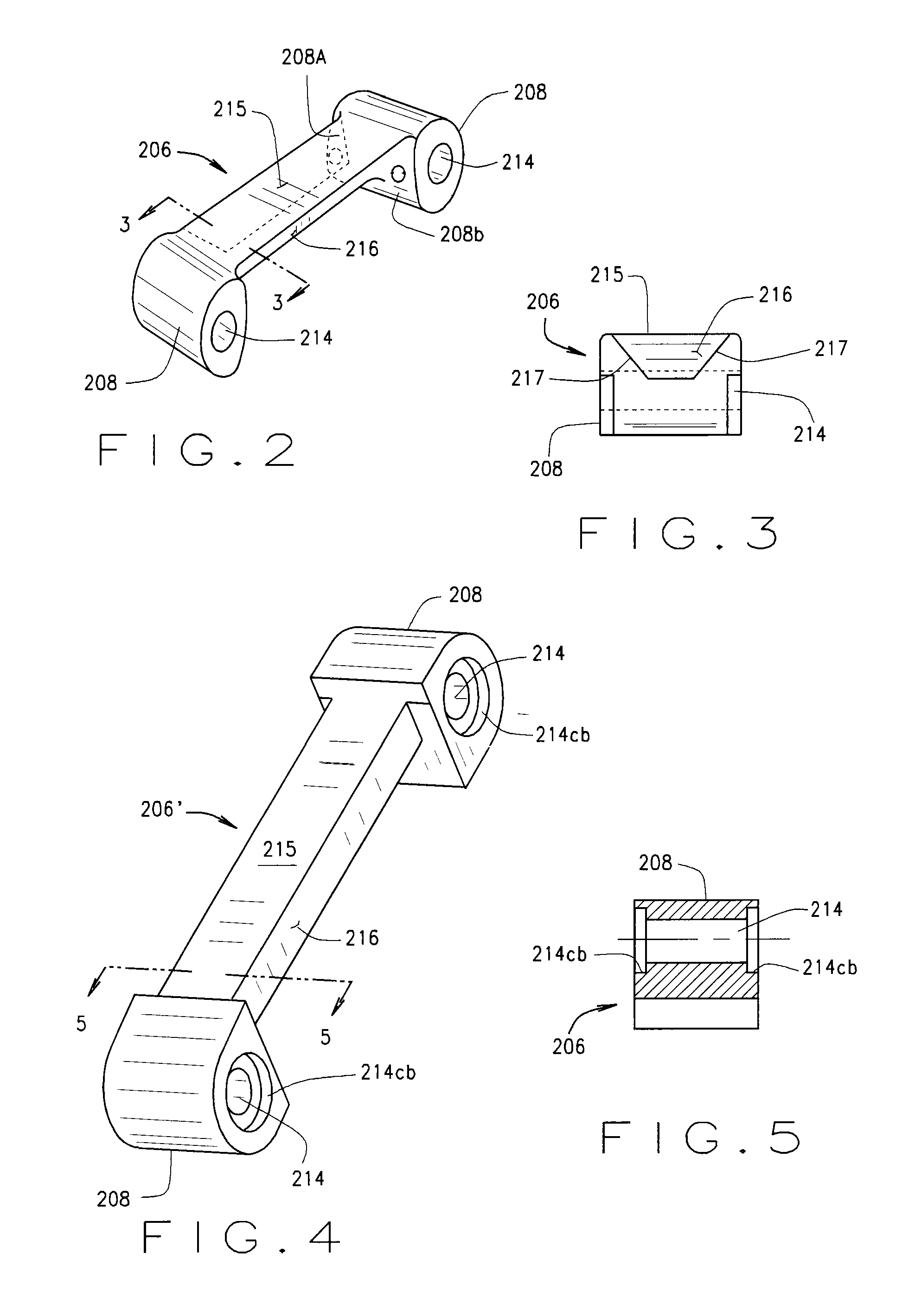
[0032]Referring to FIGS. 1, 8, and 9, a preassembled segmented bearing retainer or cage 100 comprises first circular hoop or ring 102 and a second and correspondingly sized and shaped circular hoop or ring 104. As particularly shown in FIG. 1, ring 104 is axially displaced from ring 102. Cage 100 also includes multiple discrete bridge elements 206 each of which spans the axial distance between rings 102, 104. The bridge elements are preferably made of a powdered metal material including sintered steel. Cage 100 further includes tubular spacers 110 each of which has a longitudinal bo...


PUM

PropertyMeasurementUnit
diameteraaaaaaaaaa
circumferenceaaaaaaaaaa
diameteraaaaaaaaaa

Abstract

A bearing cage assembly (100) comprises a plurality of discrete bridge elements (206) disposed between adjacent rolling elements (112) and coupled between first and second axially spaced cage support wire rings (102, 104) which are appropriately tensioned. Spacers (110) are disposed between adjacent bridge elements and engage the bridge elements in a piloted engagement. The bridge elements maintain a separation between rolling elements, retain the rolling elements within the bearing assembly, and function as a lubrication reservoir for grease lubricated bearings. Profiled surfaces on the bridge elements position the bearing cage assembly on at least one axial end of the rolling elements.

Description

CROSS-REFERENCE TO RELATED APPLICATIONS[0001]The present application is related to and claims priority from U.S. provisional patent application Ser. No. 61 / 654,159 filed Jun. 1, 2012, which is herein incorporated by reference.STATEMENT REGARDING FEDERALLY SPONSORED RESEARCH[0002]Not Applicable.BACKGROUND OF THE INVENTION[0003]The present application is generally related to large bearing cage configurations, and in particular, but not exclusively, to a cage assembly for a large diameter bearing containing multiple heavy rolling elements and including discrete bridge elements coupled between axially-spaced cage wire rings located adjacent opposite axial ends of the rolling elements.[0004]The usual approach to designing large-bearing cages (typically 1-4 meters in diameter) has been to extend the design styles for smaller, conventional bearings to the larger bearing sizes. The first and most common attempt at meeting the needs of larger bearings uses pin style cages to facilitate place...

Claims


Application Information

Patent Timeline
Patent Type & Authority Patents(United States)
IPC IPC(8): F16C33/54F16C33/50F16C43/04F16C43/06
CPCF16C33/508F16C43/04F16C43/065F16C19/364F16C33/4611F16C33/4664F16C2300/14Y10T29/49687
Inventor FOX, GERALD P.MARKS, CHRISTOPHER S.WERNER, BRIANRYBKOSKI, THOMAS J.LANDIN, HANS
Owner THE TIMKEN CO
Why Eureka
Try Eureka