Fine adjusting method of the feed amount of the boring cutter and the adjusting device thereof

a technology of adjusting device and boring cutter, which is applied in the field of fine adjustment of boring cutter feed amount and the adjusting device thereof, can solve the problems of affecting the precision of the boring hole, difficult to cooperate with each other, and difficult to manufacture elements, etc., and achieves accurate feed amount value, good linear character, and high precision

Inactive Publication Date: 2009-05-07
ZUO DEJIAN
View PDF17 Cites 8 Cited by
  • Summary
  • Abstract
  • Description
  • Claims
  • Application Information

AI Technical Summary

Benefits of technology

[0015]A dial for indicating feed amount of cutter changing in a rotary manner is provided on the worn of the turbine and worn transmission mechanism, so as to obtain accurate feed amount value.
[0016]As adopting the above technique, the boring cutter of the present invention has good linear character and high precision for fine adjusting the feed amount. The precision of the fine adjustment is up to 0.002 mm. The device has many advantages. For example, the elements of the device are simple in shape; the device has rigid structure, and is convenient to operate; due to small shift of the gravity center, the device can be used for quick cutting. The device can satisfy various work conditions of the hole machining machine, such as the boring machine, milling machine, and drilling machine.

Problems solved by technology

In this structure, there are many elements that are hard to be manufactured and are difficult to cooperate with each other.
Furthermore, there is a gap between the linear moving elements, so that the precision of the boring hole is affected, if without proper maintenance.
In addition, when the moving body is moved for a long distance, the gravity center is shifted largely, so that quick cutting can not be realized.
And the screw pitch cannot be small, so that the precision of fine adjustment is restricted.

Method used


Image

  • Fine adjusting method of the feed amount of the boring cutter and the adjusting device thereof
  • Fine adjusting method of the feed amount of the boring cutter and the adjusting device thereof
  • Fine adjusting method of the feed amount of the boring cutter and the adjusting device thereof

Examples


example 1

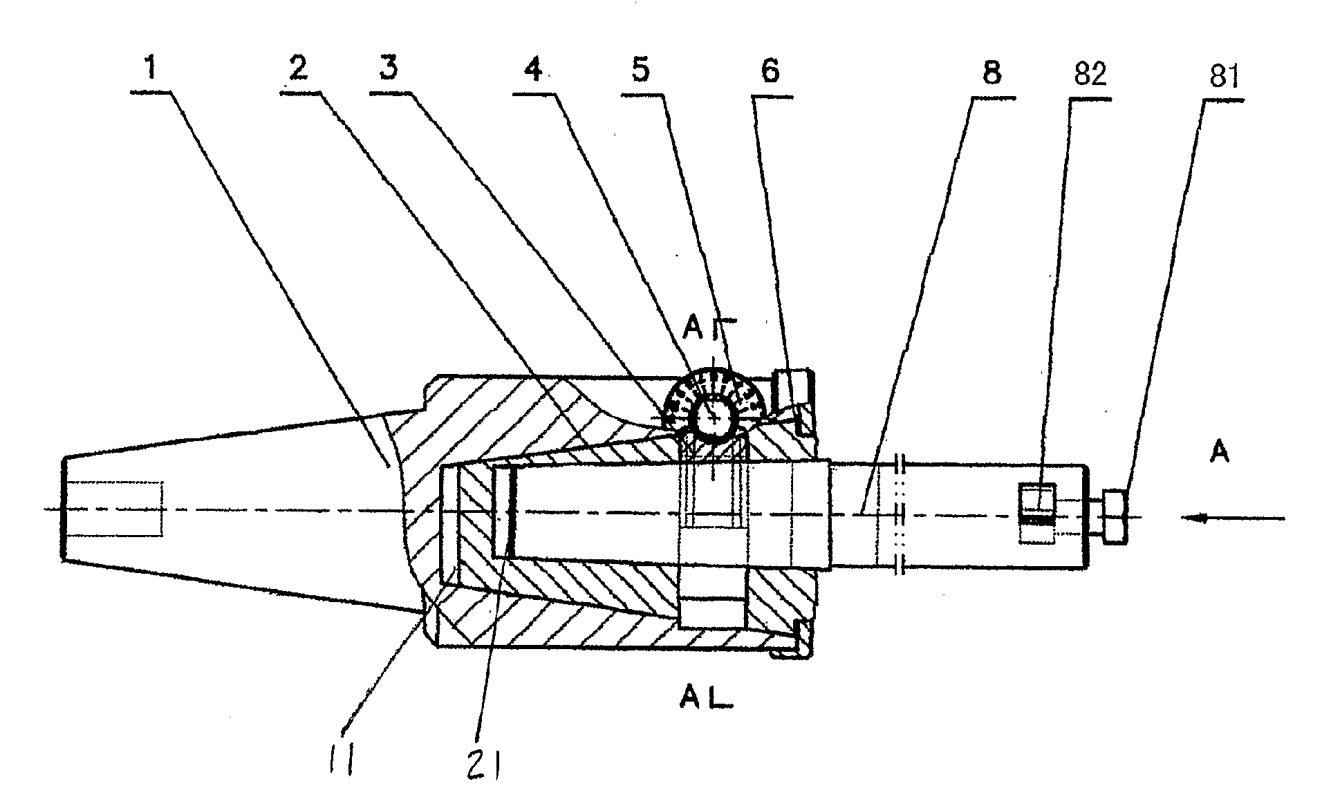
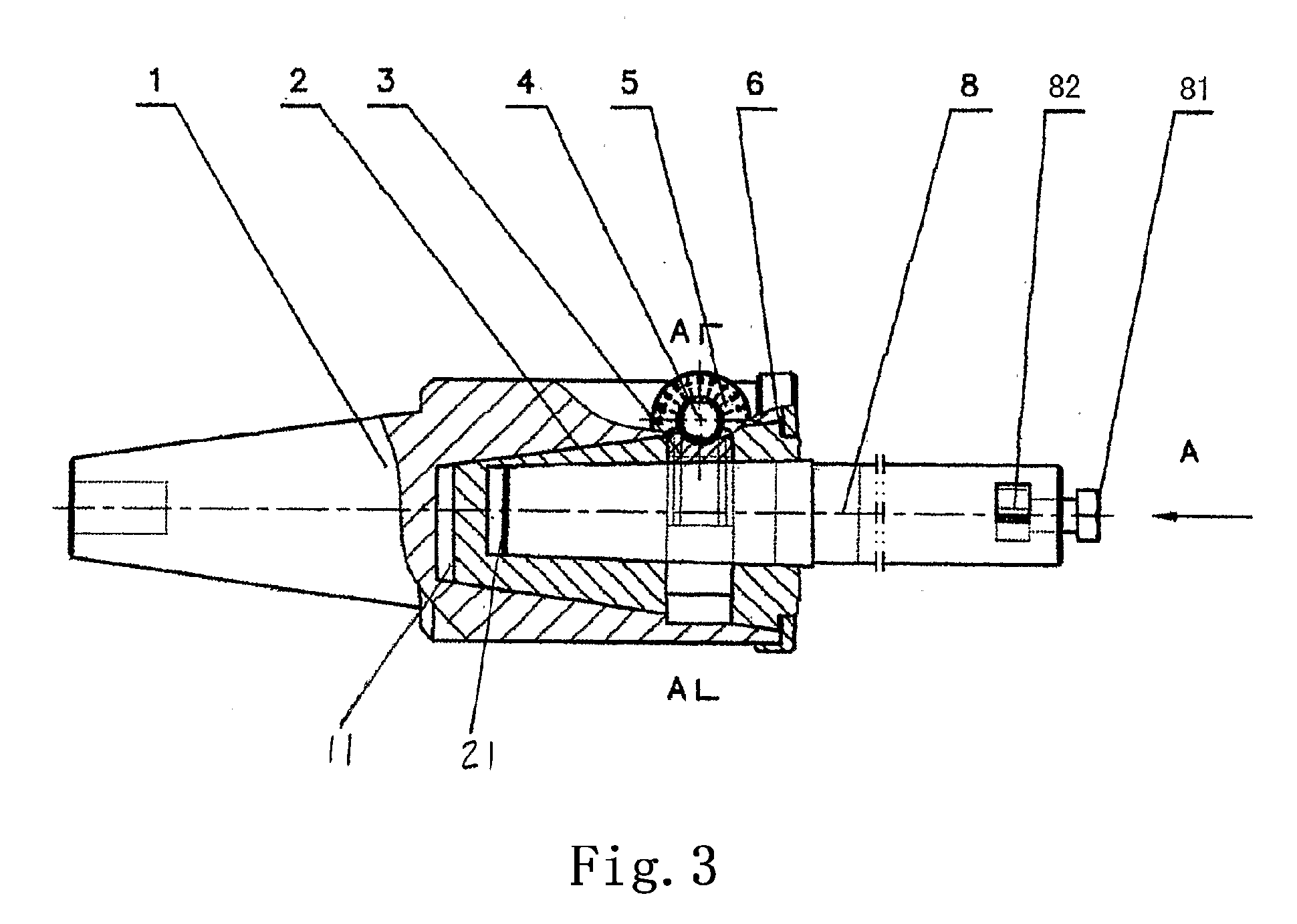
[0036]Referring to FIG. 3, FIG. 4 and FIG. 5 of the drawings, the fine adjusting device for adjusting feed amount of a cutter is applied to milling machine. The taper shank of the cutter bar 1 is engaged into the taper hole of the main shaft of the milling machine. The cutter bar 1 has a first eccentric taper hole 11 apart from the axis of the cutter bar 1. In the first eccentric taper hole 11, a rotating taper 2 is provided between a side cover threadedly connected to the cutter bar 1 and a resilient element 6. The rotating taper 2 also has a second eccentric hole 21 apart from the axis of the rotating taper 2. A changeable cutter arbor 8 is provided in the second eccentric hole 21 of the rotating taper 2. A cutter 81 is mounted on the front of the changeable cutter arbor 8 via a fastening screw 81.

[0037]A turbine 3 is mounted on the rotating taper 2, and it also can be directly incorporated onto the outer surface of the rotating taper. A worn 4 is mounted on the cutter bar 1 via a...

example 2

[0041]Referring to FIG. 6 through FIG. 9, the fine adjusting device for adjusting feed amount of a cutter is applied to a milling machine. The taper shank of the cutter bar 1 is engaged into the taper hole of the main shaft of the milling machine.

[0042]In this example, when the worn 4 rotates one circle, the feed amount change 0.5 mm. The dial 7 for indicating feed amount on the worn 4 has 50 indicating lines marked thereon, and each indicating line indicates that the feed amount changes 0.01 mm.

[0043]In the eccentric taper hole 11 of the cutter bar 1, the rotating taper 2 having a taper hole 22 therein is mounted between the resilient element 6 and a fastening cover 61 that is threadedly connected with the cutter bar 1. The axis of the taper hole 22 is coincidence with the axis of the rotating taper.

[0044]An incomplete turbine 31 of the turbine and worn mechanism is mounted on the rotating taper 2. The two sides of the worn is mounted in the worn hole 12 of the cutter bar 1 via a b...

example 3

[0051]The example 3 is applied to a machining center machine. As shown in FIG. 10, the difference from the example 2 is that the taper shank of the cutter bar is engaged with the taper hole of the axis of the machining center (ISO 7:24 50); and both linear and rotation way to change the feed amount are adopted.

[0052]The cutter 82 is threadedly connected with the changeable cutter arbor 8. A dial for indicating linear feed amount 84 is provided at the threaded connection position of the changeable cutter arbor 8. The cutter 82 has indicating lines stamped thereon.

[0053]The changeable cutter arbor 8 adjusts the feed amount via the thread thereon. The angle between the axis of the thread and the axis of the changeable cutter arbor 8 is 53 degree and 8 minute. The thread pitch is 1 mm. The dial for indicating linear feed amount 84 is equally divided to 20 parts, and the indicating precision is 0.04 mm.

[0054]Changing the feed amount in a rotary manner is adopted on the cutter bar 1. The ...


PUM

PropertyMeasurementUnit
angleaaaaaaaaaa
sizesaaaaaaaaaa
pressureaaaaaaaaaa

Abstract

A fine adjusting method of the feed amount of a boring cutter includes the following steps: a shank body rotates around its axes as the center of a circle to make the cutter tip rotate around its axes as the center of a circle which is apart away from the axes with an offset distance e therebetween so as to change the feed amount. An adjusting device which can achieve the fine adjusting method of the feed amount of the boring cutter includes: a shank body which has a tapered bore, and the axes of the tapered bore is apart away from the axes of the shank body; a rotating cone body which cooperates with the tapered hole; and the rotating cone body is provided with another tapered hole; a changeable cutter holder which is installed in the tapered hole of the rotating cone body; and a drive mechanism which mounts on the shank body and drives the rotating cone body to rotate, therefore makes the changeable cutter holder rotate so as to achieve the micro-feed of the cutter tip.

Description

BACKGROUND OF THE PRESENT INVENTION [0001]1. Field of Invention[0002]The present invention relates to a machining cutting tool, and more particularly to a method for adjusting feed amount of a cutter and an adjusting device thereof, and especially a method for adjusting feed amount of a boring cutter and an adjusting device thereof.[0003]2. Description of Related Arts[0004]As we all known, the current available fine adjusting boring cutter bar comprises a shank body having a linear guide track, a moving body engaged with the guide track, a screw stem transmission mechanism, a changeable cutter arbor, a dial for indicating linear feed amount, and a fastening screw, which is called a linear type fine adjusting boring cutter bar, as shown in FIG. 1. The moving body is driven by the screw stem transmission mechanism to move along the axis of the screw stem, so that the radial position of the moving body is changed to change the feed amount. In this structure, there are many elements tha...

Claims


Application Information

Patent Timeline
Patent Type & Authority Applications(United States)
IPC IPC(8): B23B51/00B23C1/20
CPCB23B29/03425Y10T408/8588G05B2219/50281G05B19/4166
Inventor QIU, SHOUSHAN
Owner ZUO DEJIAN
Why Eureka
Try Eureka