Double-airplane passive positioning method based on azimuth angle and pitch angle information

A passive positioning and pitch angle technology, applied in positioning, radio wave measurement systems, instruments, etc., can solve the problems of large number of observation stations, large measurement errors, and low positioning accuracy, so as to achieve easy implementation, reduce the introduction of errors, The effect of strong mobility and flexibility

Inactive Publication Date: 2019-01-15
HARBIN INST OF TECH
View PDF4 Cites 10 Cited by
  • Summary
  • Abstract
  • Description
  • Claims
  • Application Information

AI Technical Summary

Problems solved by technology

[0004] The purpose of the present invention is to solve the problems of large number of observation stations, low positioning accuracy and large measurement error when the traditional method is used for passive positioning, and propose a dual-aircraft passive positioning method based on azimuth and elevation angle information

Method used


Image

  • Double-airplane passive positioning method based on azimuth angle and pitch angle information
  • Double-airplane passive positioning method based on azimuth angle and pitch angle information
  • Double-airplane passive positioning method based on azimuth angle and pitch angle information

Examples


specific Embodiment approach 1

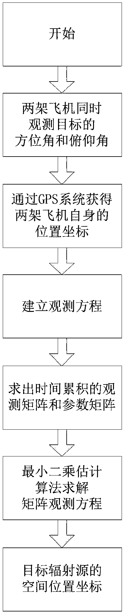
[0027] The dual-aircraft passive positioning method based on azimuth angle and elevation angle information in this embodiment, such as figure 1 As shown, the method is realized through the following steps:

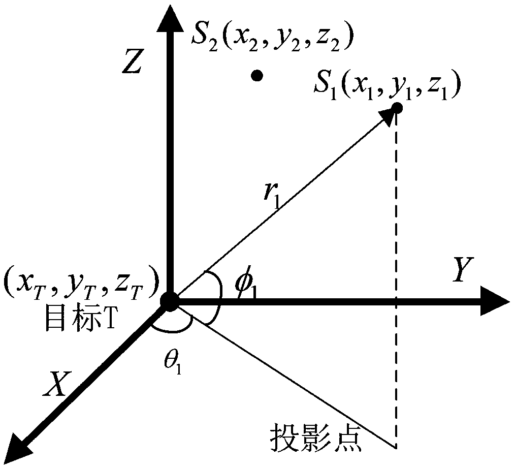
[0028] Step 1. Simulate the combat environment, and establish a space observation model between two observation aircraft and the target radiation source in the space Cartesian coordinate system; figure 2 shown;

[0029] Step 2. In the space observation model established in step 1, the relationship between the observation aircraft and the position coordinates of the target radiation source is obtained by using the observation information of the azimuth and elevation angles of the observation aircraft to observe the target radiation source arriving at the observation aircraft;

[0030] Step 3, using the space observation model established in step 1, transforming and simplifying the observation information obtained in step 2 to establish a matrix form of linear observation ...

specific Embodiment approach 2

[0034] The difference from Embodiment 1 is that in the dual-aircraft passive positioning method based on azimuth angle and pitch angle information in this embodiment, in the process of observing the relationship between the aircraft and the position coordinates of the target radiation source described in step 2, first determine The relationship between the observation plane No. 1 and the position coordinates of the target radiation source is expressed as:

[0035]

[0036] In the formula, the position coordinates of the target radiation source are u=(x T ,y T ,z T ) T , the position coordinate of the observing aircraft is S 1 =(x 1 ,y 1 ,z 1 ) T , θ 1 Indicates the azimuth angle at which the target radiation source arrives at the No. 1 observation plane, φ 1 Indicates the pitch angle at which the target radiation source reaches the No. 1 observation plane, r 1 Indicates the distance between the No. 1 observation plane and the target; θ 1 and φ 1 is the measured ...

specific Embodiment approach 3

[0041]The difference from the specific embodiment 1 or 2 is that the dual-aircraft passive positioning method based on azimuth and elevation angle information in this embodiment uses the space observation model established in step 1 described in step 3, and uses the space observation model obtained in step 2 In the process of transforming and simplifying the observation information to establish the matrix form of the linear observation equation, firstly, the process of establishing the matrix form of the linear observation equation of No. 1 observation plane is as follows:

[0042] Multiply both sides of the equal sign of the formula (2) obtained in step 2 for scalar r 1 ,but:

[0043]

[0044] Multiply the both sides of the equal sign of the formula (4) by A at the same time 1 ,Available:

[0045]

[0046] Let X=S 1 -u=(x 1 -x T ,y 1 -y T ,z 1 -z T ) T =(x,y,z) T , then formula (5) can be transformed into:

[0047]

[0048] Let A 1 The simplified form ...


PUM


Abstract

The invention relates to a double-airplane passive positioning method based on azimuth angle and pitch angle information, and belongs to the field of passive positioning. The traditional method has the disadvantages that: when passive positioning is carried out, the required observation station number is large; the positioning precision is low; and the measurement error is big. The method in the invention comprises the steps of: establishing a space observation model among two observation airplanes and a target radiation source in a space rectangular coordinate system in a simulated combat environment; observing observation information of the azimuth angle and the pitch angle, in which the target radiation source arrives at the observation airplane, by utilizing the observation airplanes;then, establishing the matrix form of a linear observation equation; establishing the joint basic observation equation of the two observation airplanes; establishing the final observation equation ofthe joint matrix form of the two observation airplanes; and then, solving the final observation equation by utilizing a least square estimation method, so that the space position coordinate of the target radiation source is obtained. The method has the advantages of being high in calculated target coordinate precision, low in complexity and calculation amount and rapid in realization speed.

Description

technical field [0001] The invention relates to a passive positioning method of an airborne platform, in particular to a dual-machine passive positioning method. Background technique [0002] The four major threats that traditional radars face: electronic jamming, stealth, anti-radiation destruction, and low-altitude penetration have prompted radars to develop in the direction of concealment and anti-jamming. Algorithmic research on passive location techniques is needed. Aiming at the defects exposed by traditional radars, and under the trend of increasingly demanding concealed attacks, the passive positioning and detection technology using passive working methods has received extensive attention and attention, and is being developed by various countries as the main positioning technology. Way. The passive detection system refers to the use of the reflection of the target on the non-cooperative radiation source that already exists in space or the electromagnetic signal rad...

Claims


Application Information

Patent Timeline
Patent Type & Authority Applications(China)
IPC IPC(8): G01S5/06
CPCG01S5/06
Inventor 任广辉魏俊杰熊阿龙冯梦飞何胜阳
Owner HARBIN INST OF TECH
Why Eureka
Try Eureka