Method for manufacturing an inductor

a manufacturing method and inductor technology, applied in the field of inductors, can solve the problems of difficult to maintain the shape of the coil conductor by itself, the interruption of automated manufacturing lines, and the likely deformation of the coil conductor, etc., to achieve the effect of improving the shape retention property, being easy to apply and effective, and being superior in mass-productivity

Inactive Publication Date: 2005-03-01
MURATA MFG CO LTD
View PDF12 Cites 22 Cited by
  • Summary
  • Abstract
  • Description
  • Claims
  • Application Information

AI Technical Summary

Benefits of technology

In order to overcome the problems described above, preferred embodiments of the present invention provide an inductor which has a greatly improved shape retaining propert

Problems solved by technology

However, according to this method for manufacturing a conventional wire-wound inductor, when a thin metal wire is used for forming a solenoid-type coil conductor, it is difficult for the coil conductor to retain its shape by itself, and as a result, deformation of the coil conductor is likely to occur.
Accordingly, when these coil

Method used


Image

  • Method for manufacturing an inductor
  • Method for manufacturing an inductor
  • Method for manufacturing an inductor

Examples


Embodiment Construction

Hereinafter, an inductor and a manufacturing method therefor according to preferred embodiments of the present invention will be described with reference to accompanying drawings.

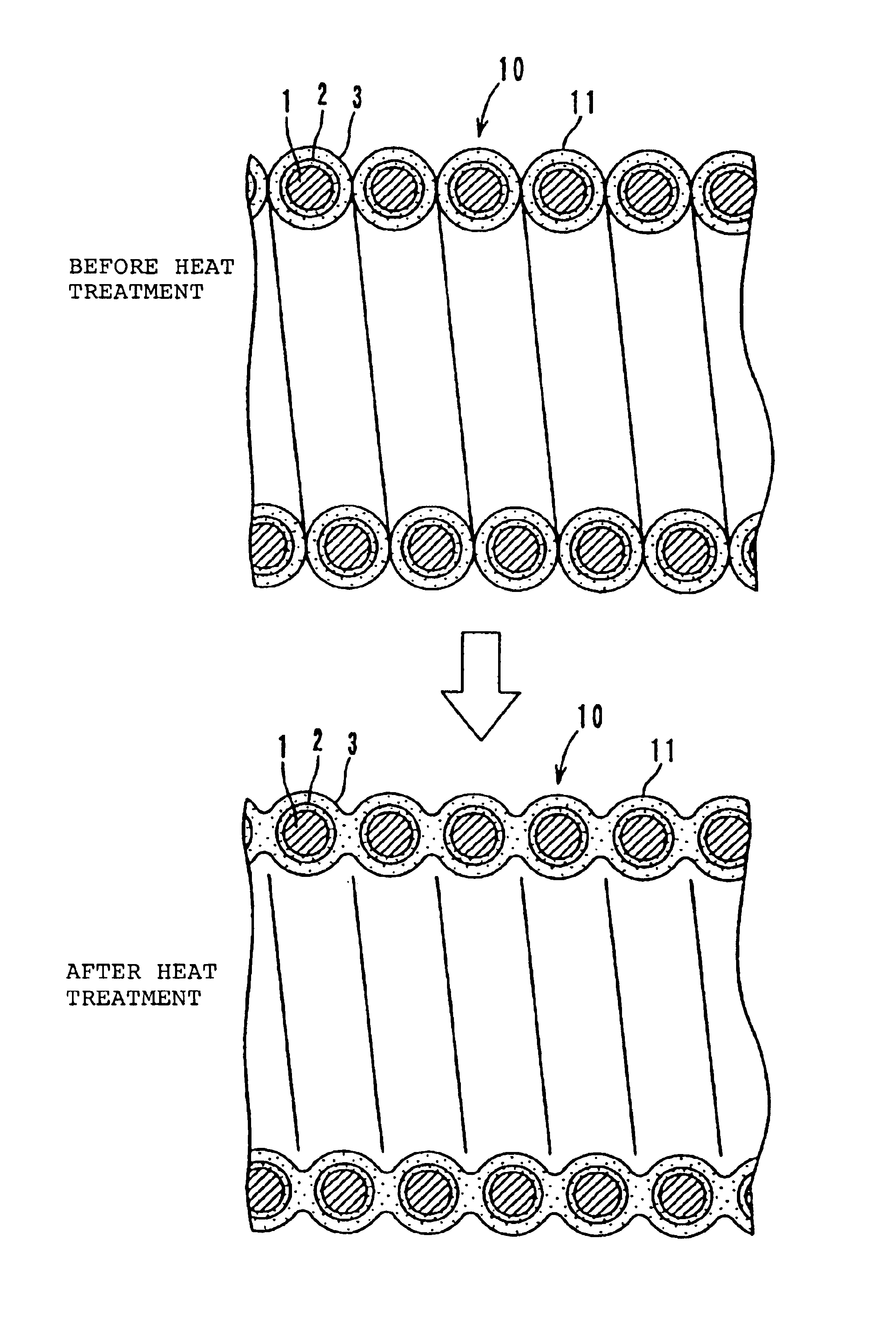
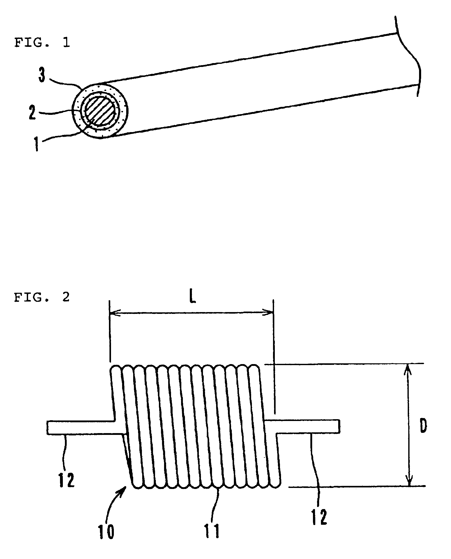
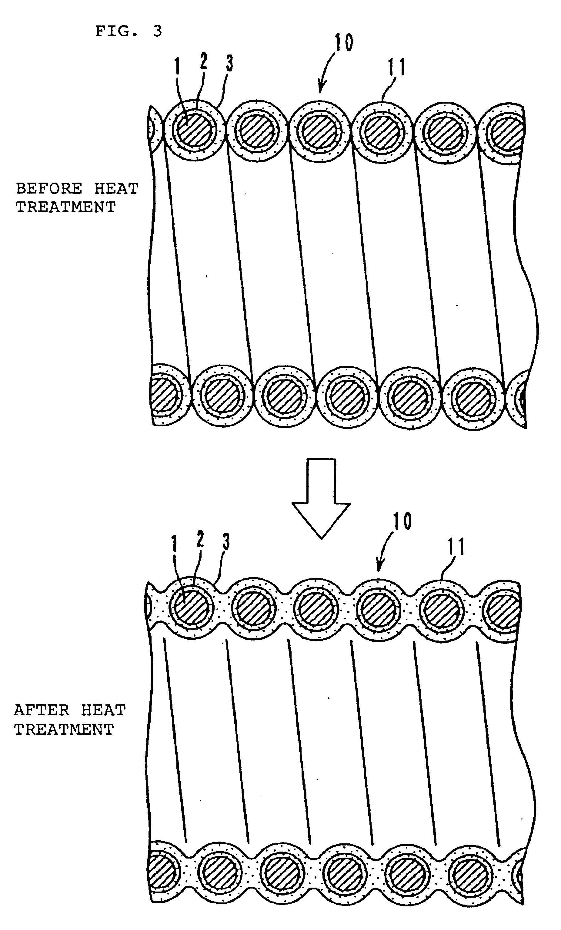
As shown in FIG. 1, a metal wire 1 provided with an insulating film 2 thereon is first prepared. As the metal wire 1, for example, a metal of about 200 μm in diameter including at least a material selected from the group consisting of Ag, Pd, Pt, Au, and Cu, or an alloy wire containing at least one metal mentioned above is preferably used. However, other suitable materials may also be used. As the insulating film 2, for example, a resin such as a polyester resin or a polyamide-imide resin, or other suitable material, is preferably used. A thermal melting resin 3 is coated on the surface of the insulating film 2 covering the metal wire 1. The thickness of the thermal melting resin 3 is, for example, approximately 1 μm. As the thermal melting resin 3, a thermosetting resin or a thermoplastic resin, such as an...


PUM

PropertyMeasurementUnit
Temperatureaaaaaaaaaa
Thicknessaaaaaaaaaa
Diameteraaaaaaaaaa

Abstract

A method for manufacturing an inductor is performed in such a manner that the surface of a metal wire provided with an insulating film thereon is coated with a thermal melting resin. The thickness of the thermal melting resin is, for example, approximately 1 μm. As the thermal melting resin, a thermoplastic resin or a thermosetting resin, such as a polyimide resin or an epoxy resin, containing 85 wt % of a powdered ferrite is used. This coated metal wire is densely wound to form a solenoid-type coil conductor. Next, the thermal melting resin is softened by a heat treatment at, for example, 180° C. and is then solidified by spontaneous cooling. Accordingly, the portions of the coil conductor adjacent to each other are bonded together by the thermal melting resin.

Description

BACKGROUND OF THE INVENTION1. Field of the InventionThe present invention relates to inductors, and more particularly, relates to a high-current inductor preferably for use in eliminating noise transmitted to and generated from electronic apparatuses and other devices, and to a manufacturing method for such an inductor.2. Description of the Related ArtRecently, in accordance with the trends towards miniaturization of circuits, higher integration thereof, and high frequency processing, high-current inductors that are compact and surface-mountable have been increasingly in demand. Conventional inductors include a wire-wound inductor having a coil conductor embedded in an encapsulating molded body. This wire-wound inductor is manufactured by densely winding a metal wire having an insulating film thereon without forming spaces between portions of the metal wire adjacent to each other to form a solenoid-type coil conductor, placing the coil conductor in a molding die, and injecting an en...

Claims


Application Information

Patent Timeline
IPC IPC(8): H01F41/00H01F41/12H01F27/32H01F27/29H01F41/04H01F17/04H01F41/10
CPCH01F41/005H01F41/122H01F27/292H01F27/327Y10T29/4902Y10T29/49071Y10T29/49117Y10T29/49076H01F41/127H01F41/10
Inventor OSHIMA, HISATOSHIKAMA, TAKESHIHAMATANI, JUNICHIFUKUTANI, IWAOSAITO, KENICHI
Owner MURATA MFG CO LTD
Why Eureka
Try Eureka