Apparatus and method for protecting a memory sharing signal control lines with other circuitry

a signal control and signal protection technology, applied in the field of electric devices, can solve the problems of memory being inadvertently written, the use of multiple circuit boards creating disadvantages regarding connections between different boards,

Inactive Publication Date: 2005-04-05
INTERDIGITAL MADISON PATENT HLDG
View PDF4 Cites 10 Cited by
  • Summary
  • Abstract
  • Description
  • Claims
  • Application Information

AI Technical Summary

Benefits of technology

In accordance with the present invention, an apparatus includes first and second circuit boards. The first circuit board includes a memory, and control circuitry for controlling at least one function of the apparatus. The second circuit board is operably coupled to the first circuit board via control lines. The second circuit board includes a controller for generating first and second control signals. The control lines transmit the first control signals from the controller to the memory when the apparatus is in a first operational state, and transmit the second control signals from the controller to the control circuitry when the apparatus is in a second operational state. To prevent inadvertent writes to the memory during the second operation state, the memory is placed in an unpowered state during the second operational state when the controller transmits the second control signals to the control circuitry. Additionally, the memory is coupled to means for preventing the memory from keeping the control lines in a low state during the unpowered state.

Problems solved by technology

Despite its advantages, the use of multiple circuit boards does create disadvantages regarding connections between different boards.
In practicing the aforementioned technique, a problem has been identified in that the memory may be inadvertently written to when the microcontroller uses the signal control lines to control an apparatus operation while the apparatus is placed in the ON state.

Method used


Image

  • Apparatus and method for protecting a memory sharing signal control lines with other circuitry
  • Apparatus and method for protecting a memory sharing signal control lines with other circuitry
  • Apparatus and method for protecting a memory sharing signal control lines with other circuitry

Examples


Embodiment Construction

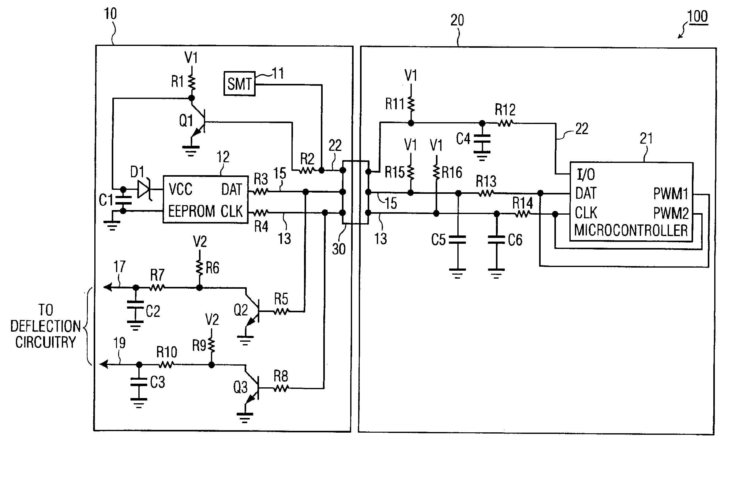
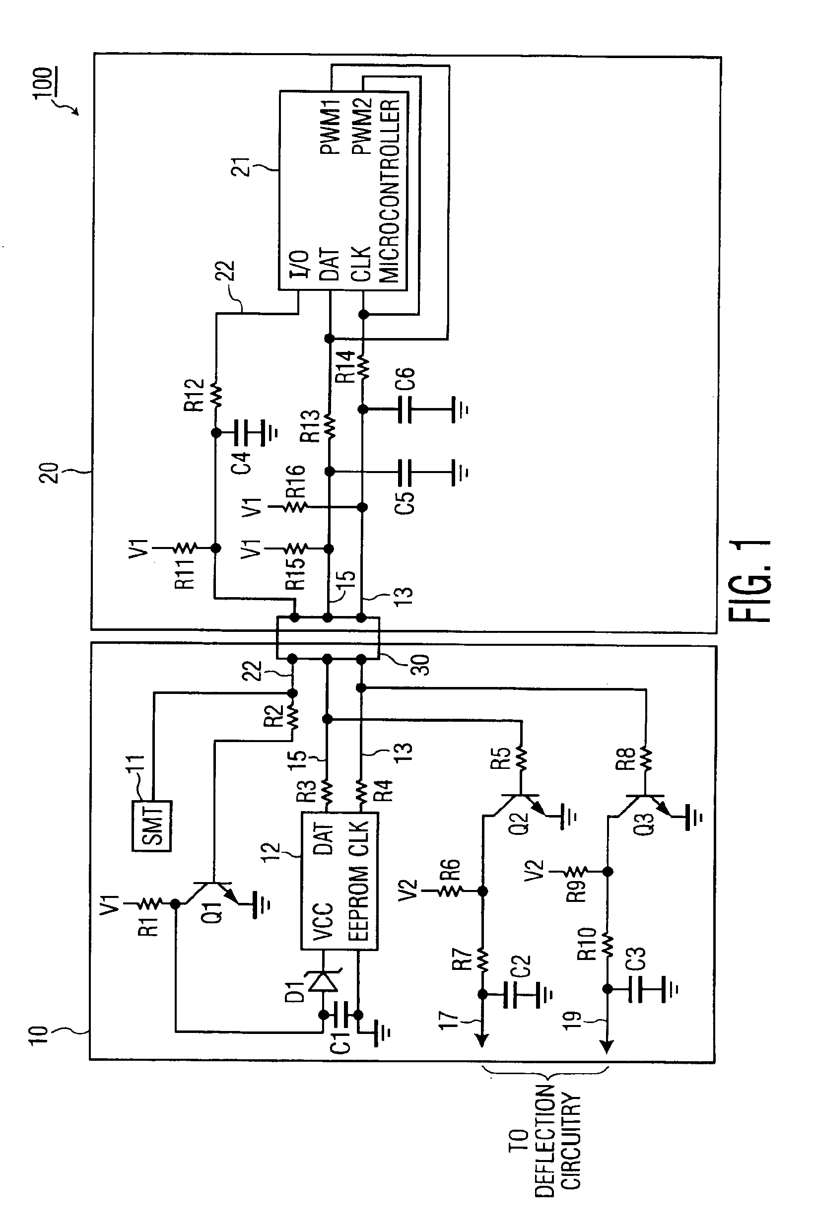
Referring now to the drawings, and more particularly to FIG. 1, a diagram of a relevant portion of an apparatus 100 suitable for implementing the present invention is shown. For purposes of example and explanation, apparatus 100 of FIG. 1 is represented as a television signal receiver. However, it is noted that the principles of the present invention may be applicable to other types of electronic devices, particularly those that utilize multiple circuit boards connected together.

Receiver 100 of FIG. 1 comprises a first circuit board 10, a second circuit board 20, and a board connector 30. According to an exemplary embodiment, first circuit board 10 enables operations related to power supply and deflection functions of receiver 100, and second circuit board 20 enables operations related to signal processing functions of receiver 100. First board 10 is electrically connected to second circuit board 20 via board connector 30.

First circuit board 10 includes a switch mode transformer (“S...


PUM


Abstract

An apparatus such as a television signal receiver includes first and second circuit boards. The first circuit board includes a memory, and control circuitry for controlling at least one function of the apparatus. The second circuit board is operably coupled to the first circuit board via control lines. The second circuit board includes a controller for generating first and second control signals. The control lines transmit the first control signals from the controller to the memory when the apparatus is in a first operational state, and transmit the second control signals from the controller to the control circuitry when the apparatus is in a second operational state. To prevent inadvertent writes to the memory during the second operational state, the controller places the memory in an unpowered state when the controller transmits the second control signals to the control circuitry. Also, means are provided to prevent the memory from keeping the control lines in one state, for example, low level, during the unpowered state to allow communications to continue on the control lines.

Description

BACKGROUND OF THE INVENTION(1) Field of the InventionThe present invention generally relates to electrical devices such as television signal receivers, and more particularly, to a technique for protecting a memory included in such a device from being inadvertently written to when, for example, signal control lines connected to the memory are shared between different devices.(2) Description of the Related ArtElectrical devices such as television signal receivers often include one or more circuit boards. Each circuit board typically has attached thereto electrical components, such as integrated circuits (“ICs”) and other elements, which enable various device operations to be performed. Prior designs for television signal receivers often employed only a single circuit board. With these prior designs, a primary incentive was to maximize the use of board area. However, since only one circuit board was used, no issues regarding connections between different circuit boards existed.Current ...

Claims


Application Information

Patent Timeline
Patent Type & Authority Patents(United States)
IPC IPC(8): H04N5/44H04N5/63G06F12/14G06F13/42G06F21/60G06F21/79
CPCH04N5/44H04N21/4436H04N21/426G06F2213/0016H04N21/4435H04N5/63G06F13/42G06F12/14
Inventor SCHNELLENBERGER, JOHN RYAN
Owner INTERDIGITAL MADISON PATENT HLDG
Why Eureka
Try Eureka