Method to shorten crystal oscillator's startup time

a crystal oscillator and startup time technology, applied in the field of crystal oscillators, can solve the problems of low startup time, control loop, high phase noise performance, etc., and achieve the effect of shortening the startup time of the oscillator, automatic amplitude control, and open loop gain of aa

Active Publication Date: 2014-05-27
TELEFON AB LM ERICSSON (PUBL)
View PDF9 Cites 3 Cited by
  • Summary
  • Abstract
  • Description
  • Claims
  • Application Information

AI Technical Summary

Benefits of technology

[0006]To shorten the oscillator startup time, the open loop gain of AAC (Automatic Amplitude Control) needs to be increased when the oscillator begins oscillating. But, to keep the phase noise performance, the transconductance (gm) of the bias transistor should be made larger than the tail current transistor from small to large that will shorten the startup time and keep the phase noise performance acceptable.
[0007]In the present invention, a control signal created by an internal circuit is used to shorten the startup time. At the first step, the oscillator starts at fast speed and low phase noise state. At the second step, the control signal is changed and oscillator goes to high phase noise state by spending a little more oscillating time. The internal control circuit consumes very low quiescent current. The method of the present invention shortens approximately 20% of the start up time while keeping acceptable phase noise performance.
[0008]The crystal oscillator of the present invention has fast startup, stable phase noise performance, and uses an internally generated control signal.

Problems solved by technology

These applications require a crystal oscillator circuit that has high phase noise performance and a low startup time.
However, the control loop is always ON and injects noise around clock edges.
This means that the AAC noise dominates the phase noise of the pierce crystal oscillator.
However, this will decrease the open loop gain of the AAC that leads to a longer the startup time.

Method used


Image

  • Method to shorten crystal oscillator's startup time
  • Method to shorten crystal oscillator's startup time
  • Method to shorten crystal oscillator's startup time

Examples


first embodiment

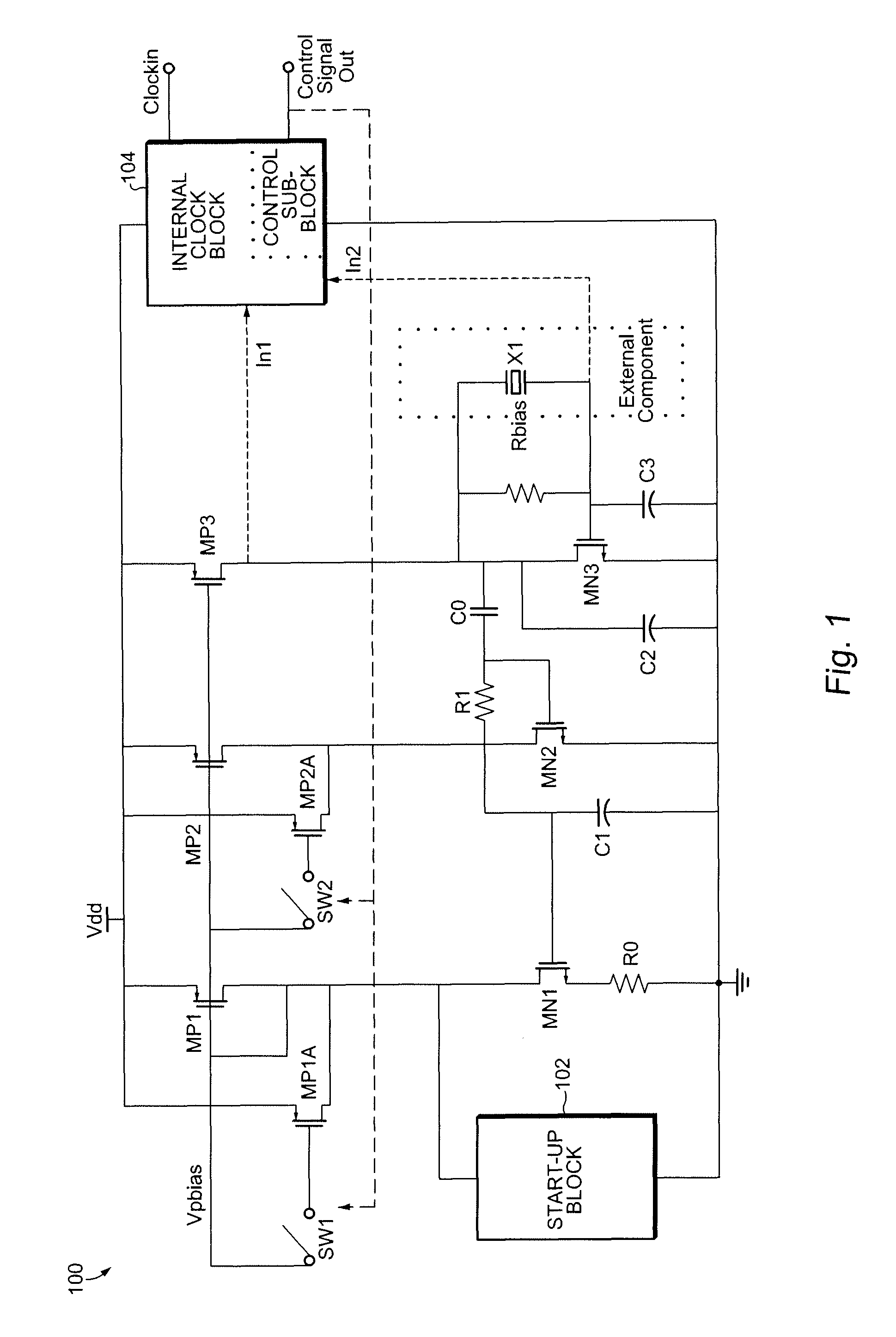
[0013]Referring now to FIG. 1 an oscillator circuit 100 according to the present invention comprises an amplifier, an AAC loop, a startup circuit 102, an internal clock block 104 including a control signal block, as well as controlled switches and transistors. The Pierce crystal oscillator circuit 100 further comprises a crystal (X1, which is generally an external component), load capacitors (C2 coupled to the drain of transistor MN3 and C3 coupled to the gate of transistor MN3), and a bias resistor (Rbias) across the crystal.

[0014]The amplifier includes transistors MN3 and MP3. The AAC loop includes transistors MN1, MN2, MP1 (and MP1A), MP2 (and MP2A), R0, Co, R1 and C1. Capacitor C0 is a DC-blocking capacitor, which couples the oscillating signal from the drain of transistor MN3. The combination of resistor R1 and capacitor C1 is a low-pass filter. A self bias circuit is formed by transistors MN1, MN2, MP1, MP2 and resistor R0. The bias transistor is split up into two parts by a s...

second embodiment

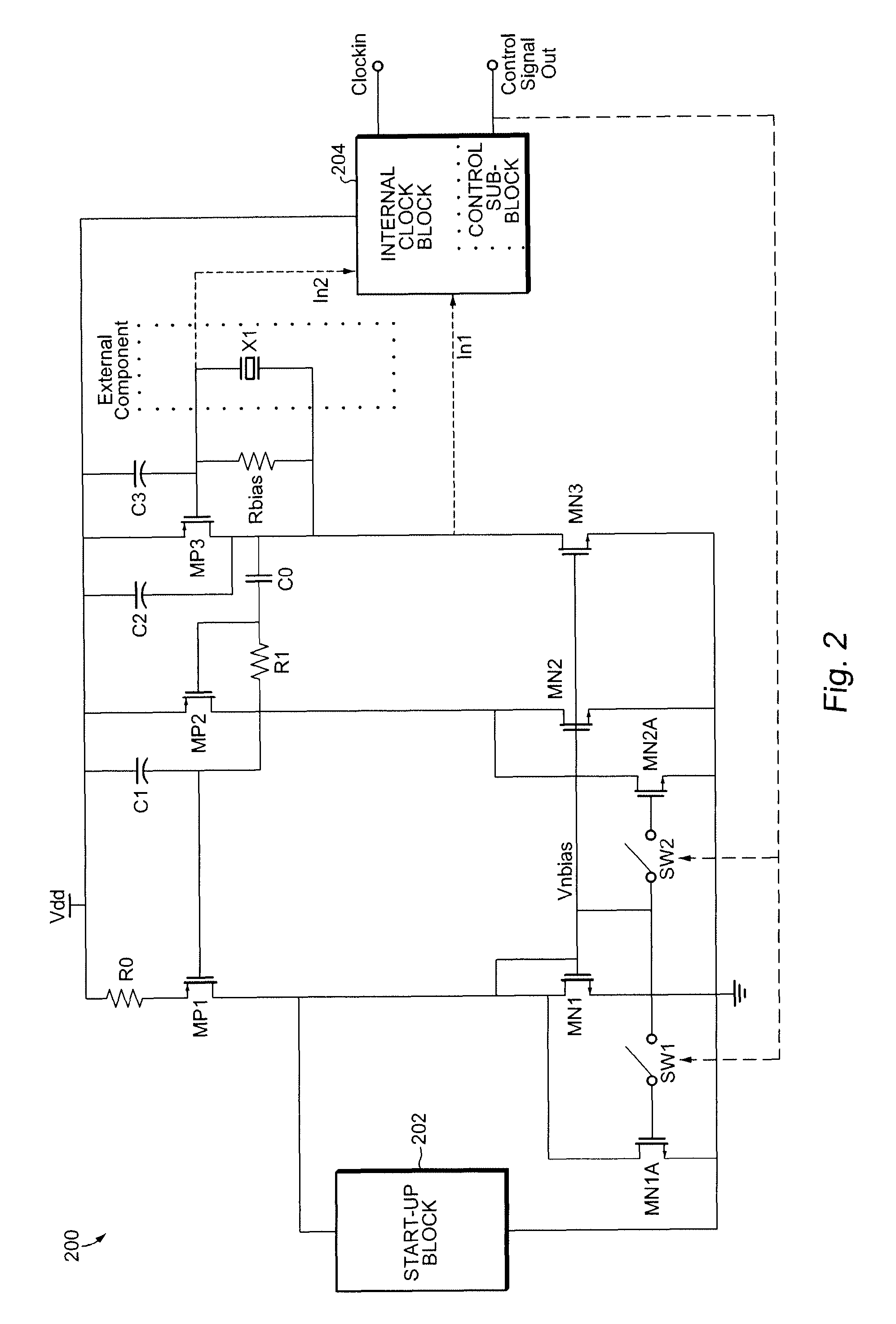
[0022]Referring now to FIG. 2 an oscillator circuit 200 according to the present invention comprises an amplifier, an AAC loop, a startup circuit 202, an internal clock block 204 including a control signal block, as well as controlled switches and transistors. The Pierce crystal oscillator circuit 200 further comprises a crystal (X1, which is generally an external component), load capacitors (C2 coupled to the drain of transistor MP3 and C3 coupled to the gate of transistor MP3), and a bias resistor (Rbias) across the crystal.

[0023]The amplifier includes transistors MN3 and MP3. The AAC loop includes transistors MN1 (and MN1A), MN2 (and MN2A), MP1, MP2, R0, Co, R1 and C1. Capacitor C0 is a DC-blocking capacitor, which couples the oscillating signal from the drain of transistor MN3. The combination of resistor R1 and capacitor C1 is a low-pass filter. A self bias circuit is formed by transistors MN1, MN2, MP1, MP2 and resistor R0. The bias transistor is split up into two parts by a s...

third embodiment

[0028]In the invention, the circuit shown in FIG. 1 can be “flipped” as is known in the art, wherein the PMOS and NMOS transistors are swapped, the polarities of the signals changed, and the power and ground rails are switched.


PUM


Abstract

An oscillator circuit includes an amplifier including at least two terminals for receiving a crystal and an automatic amplitude control loop coupled to the amplifier including biasing circuitry switched between a first operational mode and a second operational mode. The first operational mode occurs during an initial time period and the second operational mode occurs after the initial time period is expired. The biasing circuitry includes first and second PMOS transistor circuits, each transistor circuit including an unswitched PMOS transistor and a switched PMOS transistor. Alternatively, the biasing circuitry can include first and second NMOS transistor circuits, each transistor circuit including an unswitched NMOS transistor and a switched NMOS transistor. The biasing circuitry is under control of an internally generated control signal.

Description

BACKGROUND OF THE INVENTION[0001]The present invention is related to crystal oscillators and more particularly a method for decreasing the oscillator startup time.[0002]At the present time, a 32,768 Hz clock signal is used in most portable applications using a crystal oscillator. These applications require a crystal oscillator circuit that has high phase noise performance and a low startup time.[0003]Traditional pierce crystal oscillator typically use an Automatic Amplitude Control loop (AAC) to keep the amplitude constant with process and temperature. However, the control loop is always ON and injects noise around clock edges. This means that the AAC noise dominates the phase noise of the pierce crystal oscillator. To increase phase noise performance, typical designs often set the transconductance of a bias transistor larger than the tail current of the amplifier to decrease the noise impact from the bias circuit. However, this will decrease the open loop gain of the AAC that leads...

Claims


Application Information

Patent Timeline
Patent Type & Authority Patents(United States)
IPC IPC(8): H03B5/32
CPCH03B5/364H03L7/00H03L3/00H03B2200/0094
Inventor HUANG, SHUIWENHUANG, LIN
Owner TELEFON AB LM ERICSSON (PUBL)
Why Eureka
Try Eureka