Battery temperature control device

a battery and temperature control technology, applied in the direction of batteries, safety/protection circuits, cell components, etc., can solve the problems of battery freezing, false above-described restart time, and inability to run the electric vehicle which runs on the battery power

Active Publication Date: 2016-01-26
NISSAN MOTOR CO LTD
View PDF14 Cites 1 Cited by
  • Summary
  • Abstract
  • Description
  • Claims
  • Application Information

AI Technical Summary

Benefits of technology

[0022]Consequently, even when the heater is not initially switched to the ON state, it is possible to surely control the temperature of the battery by the warming by the heater when the battery is in the above-described temperature low state since then.
[0023]Therefore, it is possible to avoid that the battery is remained in the temperature low state, and to prevent from falling into a worst situation such as a situation in which the battery electrolyte is frozen.

Problems solved by technology

Accordingly, there is caused a problem that the electric vehicle which runs by the battery electric power cannot run.
However, when the temperature sensor is in the failure state, the above-described restart time becomes false.
There is caused a problem that the battery is frozen.

Method used


Image

  • Battery temperature control device
  • Battery temperature control device
  • Battery temperature control device

Examples


first embodiment

Structure of First Embodiment

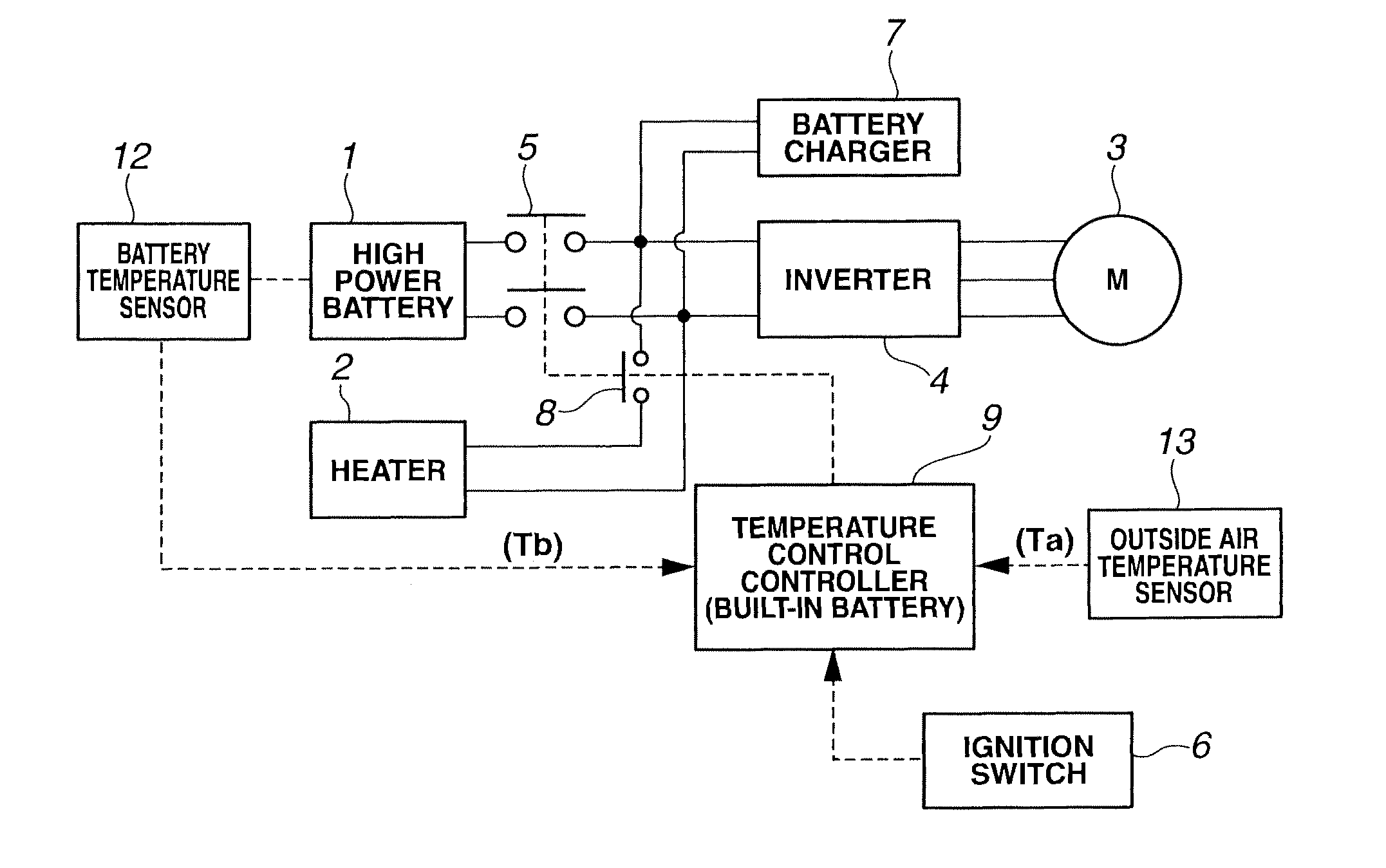
[0035]FIG. 1 is a control system view showing a battery temperature control device according to a first embodiment of the present invention. In this embodiment, this battery temperature control device is a device for controlling a temperature of a high power (high rate) battery 1 of an electric vehicle such as an electric automobile and a hybrid vehicle.

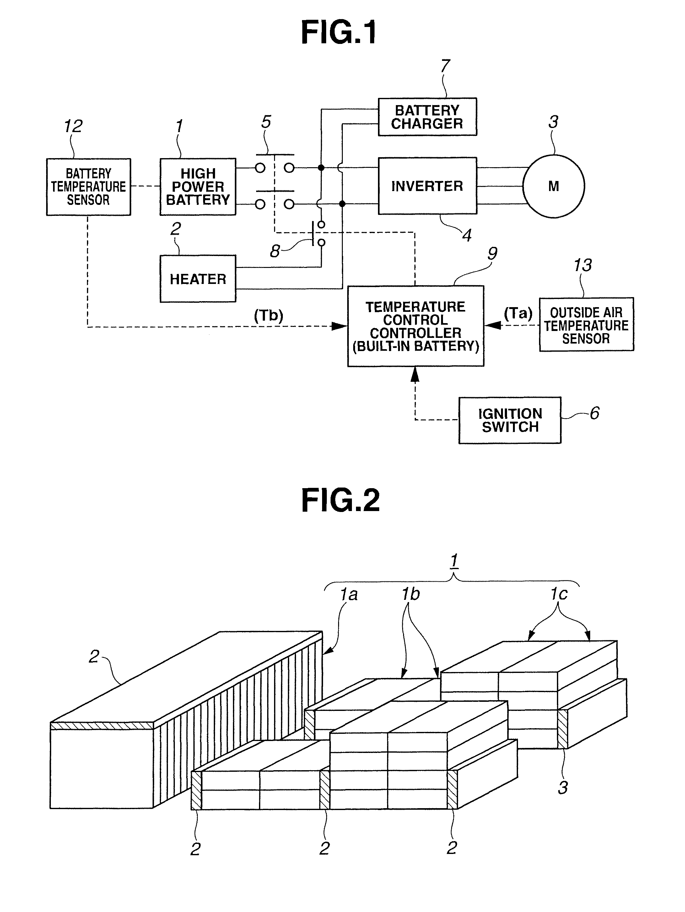
[0036]Moreover, as shown in, for example, FIG. 2, in high power battery 1, a plurality of battery modules 1a, 1b, and 1c each having a plurality of battery shells stacked are integrally united as one set. High power battery 1 is a battery with a high capacity which can serve for driving the motor.

[0037]In this case, in the battery module 1a, the battery shells are disposed in a vertical direction, and stacked in a vehicle widthwise direction. The battery module 1a is positioned below a floor panel of a rear seat of the vehicle.

[0038]In the battery module 1b, the battery shells are disposed in a traverse (...

second embodiment

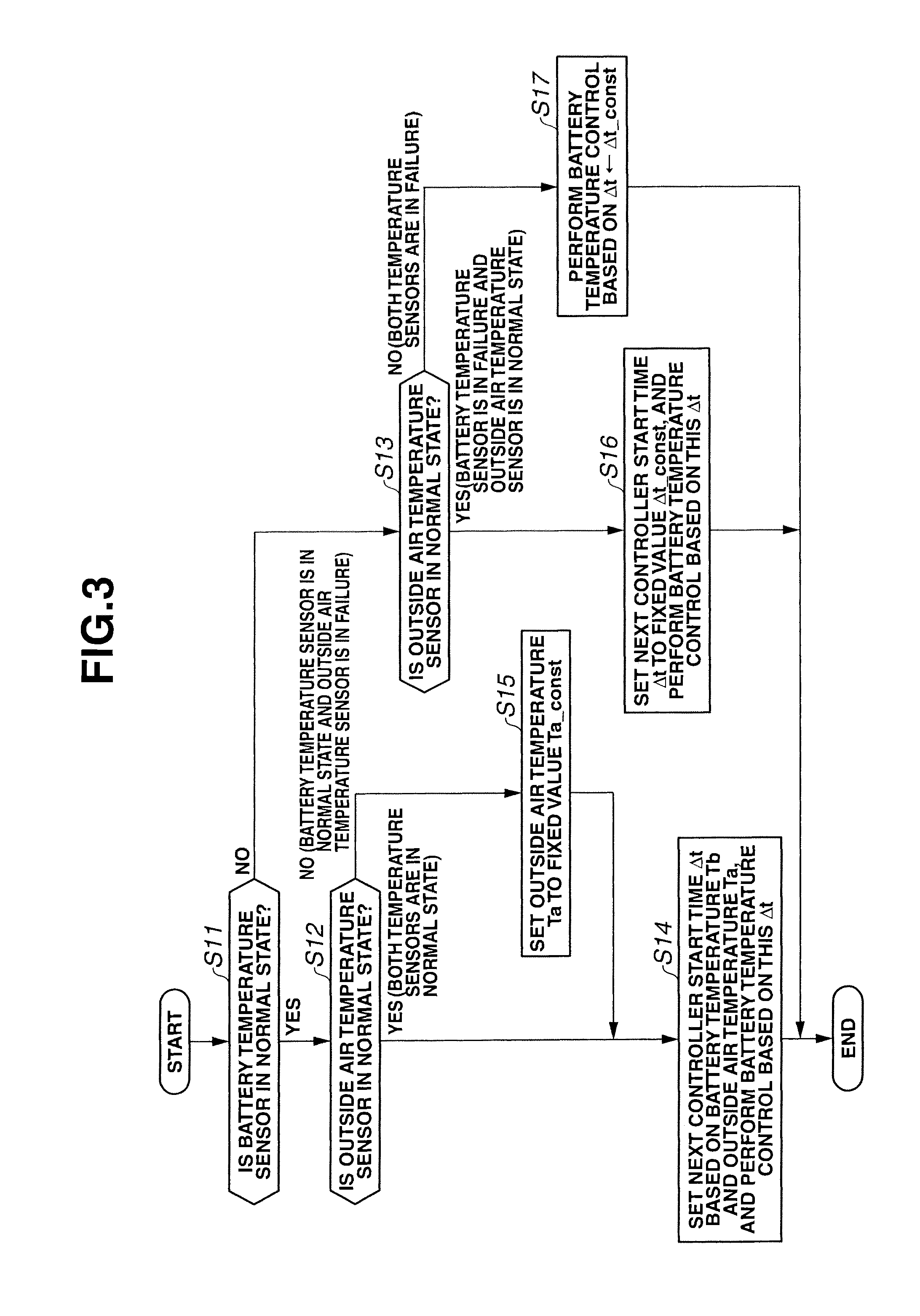
[0165]FIG. 8 is a battery temperature control program of a battery temperature control device according to a second embodiment of the present invention.

[0166]The present embodiment basically has a structure identical to that of the first embodiment. The battery temperature control program of FIG. 8 is performed in place of the battery temperature control program shown in FIG. 3 according to the first embodiment.

[0167]Step S11-step S14, and step S17 of FIG. 8 are steps which perform, respectively, the operations identical to those of the same symbols of FIG. 3. Accordingly, the illustrations are omitted. The only steps S21-step S23 which are different from FIG. 3 are illustrated.

[0168]When it is judged that the battery temperature sensor 12 is in the normal state at step S11 and however it is judged that the outside air temperature sensor 13 is in the abnormal state at step S12, that is, when the outside air temperature sensor 13 is in the failure state, the control proceeds to step ...


PUM

PropertyMeasurementUnit
freezing point temperatureaaaaaaaaaa
temperatureaaaaaaaaaa

Abstract

Even when temperature sensors (12, 13) used in a device for warming a battery (1) being not in use by using a battery-driven heater (2) have failed, the battery (1) is prevented from freezing. Based on a battery temperature (Tb) and an outside air temperature (Ta), times (Δt1 to Δt8) during which Tb will decrease down to a warming start temperature (Tb_start) are each set to the next controller startup time (Δt). A controller (9) is started up every Δt, at t2, t3, and t4, and checks whether Tb<Tb_start is satisfied or not. At t4 when Tb<Tb_start is satisfied, a heater (2) is battery-driven to warm the battery (1). After t0 when the outside air temperature sensor (13) fails, the outside air temperature (Ta) is set to a fixed value (Ta_const) and based on this Ta=Ta_const and the battery temperature (Tb), the above control is repeated. Accordingly, it is unlikely that the temperature information (Ta) from the outside air temperature sensor (13) that is at fault causes Δt to become extremely long like ∞, so that it is avoided that the heater (2) cannot be operated because the controller (9) cannot be started up and the battery (1) freezes.

Description

TECHNICAL FIELD[0001]This invention relates to a battery temperature control device configured to prevent a temperature decrease of a battery which is used in a cold region, in particular, a temperature decrease during non-use.BACKGROUND ART[0002]In a battery which may be used in a cold area like a battery mounted on an electric vehicle, a battery electrolyte may be frozen during non-use.[0003]When the temperature of the battery is lowered, an available input and output electric power of the battery is lowered by an increase of an internal resistance although a state of charge SOC is not lowered. The available input and output electric power finally becomes 0 when the battery electrolyte is frozen. The electric vehicle which uses the battery as an energy source for running cannot run.[0004]Accordingly, there is needed a battery temperature control device configured to control the temperature by warming the battery by a heater before the temperature is lowered to be a state in which ...

Claims


Application Information

Patent Timeline
Patent Type & Authority Patents(United States)
IPC IPC(8): H01M10/615H02J7/00H01M10/633H01M10/635H01M10/48H01M10/625H01M2/10H01M10/6571H01M10/60H01M10/637H01M10/647H01M50/204
CPCH01M10/625H01M10/486H01M10/615H01M10/633H02J7/0021H02J7/0029H01M2/1077H01M10/6571H01M2220/20Y02T10/7055Y02T10/70Y02E60/10H02J7/0013H02J7/0047H01M50/204H01M10/635
Inventor TAKANEZAWA, YUKITAKANO, ATSUSHIIIMORI, TAKASHIOKINO, KAZUHIKONIIOKA, HISASHIYAMAMOTO, NAOKI
Owner NISSAN MOTOR CO LTD
Why Eureka
Try Eureka