
Brazing method

a brazing method and aluminum material technology, applied in the direction of soldering apparatus, manufacturing tools, light and heating equipment, etc., can solve the problems of inability to use, degrade the quality of the brazing joint(s), and easy deformation of the brazing surface, so as to reduce the consumption of flux, the effect of low oxygen concentration state and easy brazing

Active Publication Date: 2018-12-11
FURUKAWA SKY ALUMINUM CORP
View PDF160 Cites 1 Cited by
  • Summary
  • Abstract
  • Description
  • Claims
  • Application Information

AI Technical Summary

Benefits of technology

[0013]The present invention has been made in view of such a background, and it is intended to provide a brazing method that can be readily applied in a mass-production facility, can easily simplify the manufacturing process and can stabilize the quality of (a) brazed joint(s).
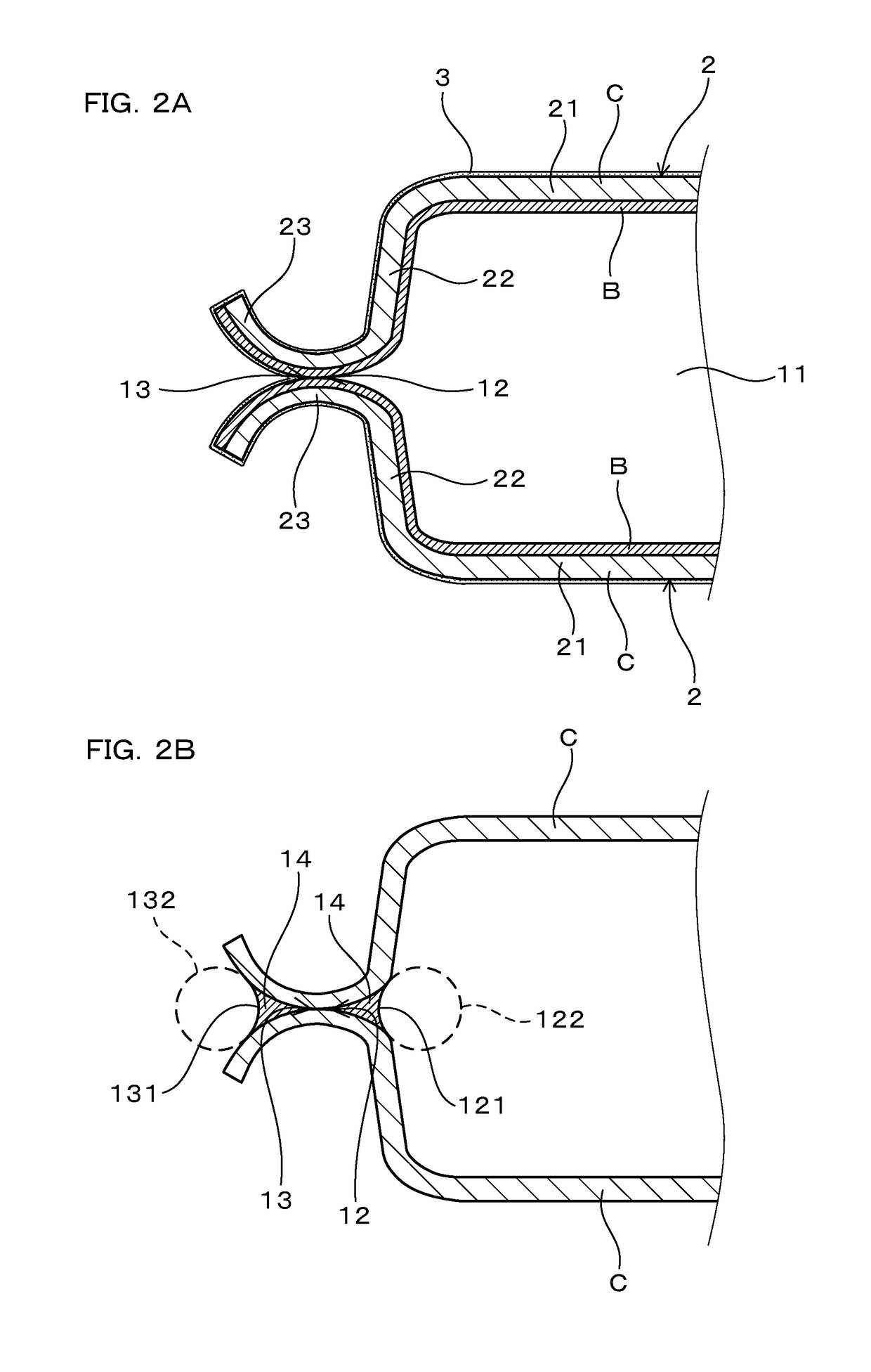
[0019]In the above-mentioned brazing method, the object to be processed includes an inner join part that faces a hollow portion and an outer join part that faces an external space. Because the inner join part faces the hollow portion into which the atmosphere of the external space is impeded from flowing, a low oxygen concentration state in the atmosphere can be easily maintained. Therefore, the inner join part is easily be brazed without using flux. On the other hand, because the oxygen concentration in the atmosphere at the outer join part that faces the external space tends to fluctuate, it is necessary to use a flux for brazing. As mentioned above, the object to be processed has two kinds of join parts that differ in the methods that are suitable for brazing them.
[0020]With regard to this, the brazing sheet to be used for brazing the object to be processed includes the core layer and the filler metal layer, in which the Mg contents are restricted in both to less than the specified amounts. Consequently, the brazing sheet can reduce the consumption of flux due to a reaction with Mg, and can improve the brazeability of the outer join part by using the flux. Thus, by applying the flux only onto the filler metal layer that is present in the outer join part, the brazing method makes it possible to form a satisfactory brazed joint at the outer join part where the oxygen concentration in atmosphere tends to fluctuate.
[0021]Moreover, the filler metal layer contains at least one of Li (lithium) and Be (beryllium), and Bi (bismuth). Li and Be function to break up the oxide films on the surface of an aluminum material. In addition, Bi has the effect of promoting the break-up of the oxide films by Li and Be. Consequently, the brazing sheet makes it possible to form a satisfactory brazed joint at the inner join part, where a low oxygen concentration state can be stably maintained, without using any flux.
[0022]As a result, the brazing method makes it possible to form satisfactory brazed joints collectively at both the outer join part and the inner join part, which differ in the conditions for forming a satisfactory brazed joint, and to stabilize the quality of the brazed joints. Moreover, because the brazing method makes it possible to perform brazing of the outer join part, where the oxygen concentration tends to fluctuate, by using flux, it is not necessary to strictly control the oxygen concentration. Therefore, the brazing method can be readily applied in a mass-production facility. In addition, because the brazing method does not require flux to be applied to the inner join part, it is not necessary to apply flux in advance before assembling the object to be processed. Consequently, the brazing method easily makes it possible to simplify the brazing manufacturing process.

Problems solved by technology

A method of performing brazing in an inert gas atmosphere without using any flux is problematic in that brazeability easily degrades when the oxygen concentration in the atmosphere increases.
For that reason, when this method is applied in a mass-production facility, there is a risk that the quality of the brazed joint(s) will degrade depending on the shape and the structure of the object to be processed, and the location(s) at which the brazed joint(s) is (are) formed.
However, because the oxygen concentration inside the brazing furnace fluctuates owing to various factors, it is difficult to maintain a low oxygen concentration state outside of the hollow structure.
Consequently, if the brazing filler is exposed on the exterior of the hollow structure during brazing, the brazeability on the exterior side of the hollow structure tends to degrade.
Therefore, there is a risk that the brazing filler will become insufficient on the exterior side of the hollow structure, where brazeability is inferior, and thereby brazing failures such as tearing of fillets will occur.
However, a fluoride-based flux is problematic in that it reacts with Mg contained in the brazing filler and consumes Mg, thereby deteriorating the effect of breaking up the oxide films.
Therefore, if the flux application amount is not sufficient, there is a risk that the brazeability on the exterior side of the hollow structure will not be improved sufficiently.
On the other hand, if the flux application amount is increased in order to improve the brazeability on the exterior side of the hollow structure, there is a risk that the flux will melt and penetrate through the brazing filler into the interior of the hollow structure during brazing, thereby degrading the brazeability of the interior of the hollow structure.

Method used


Image

  • Brazing method
  • Brazing method
  • Brazing method

Examples


working examples

Example 1

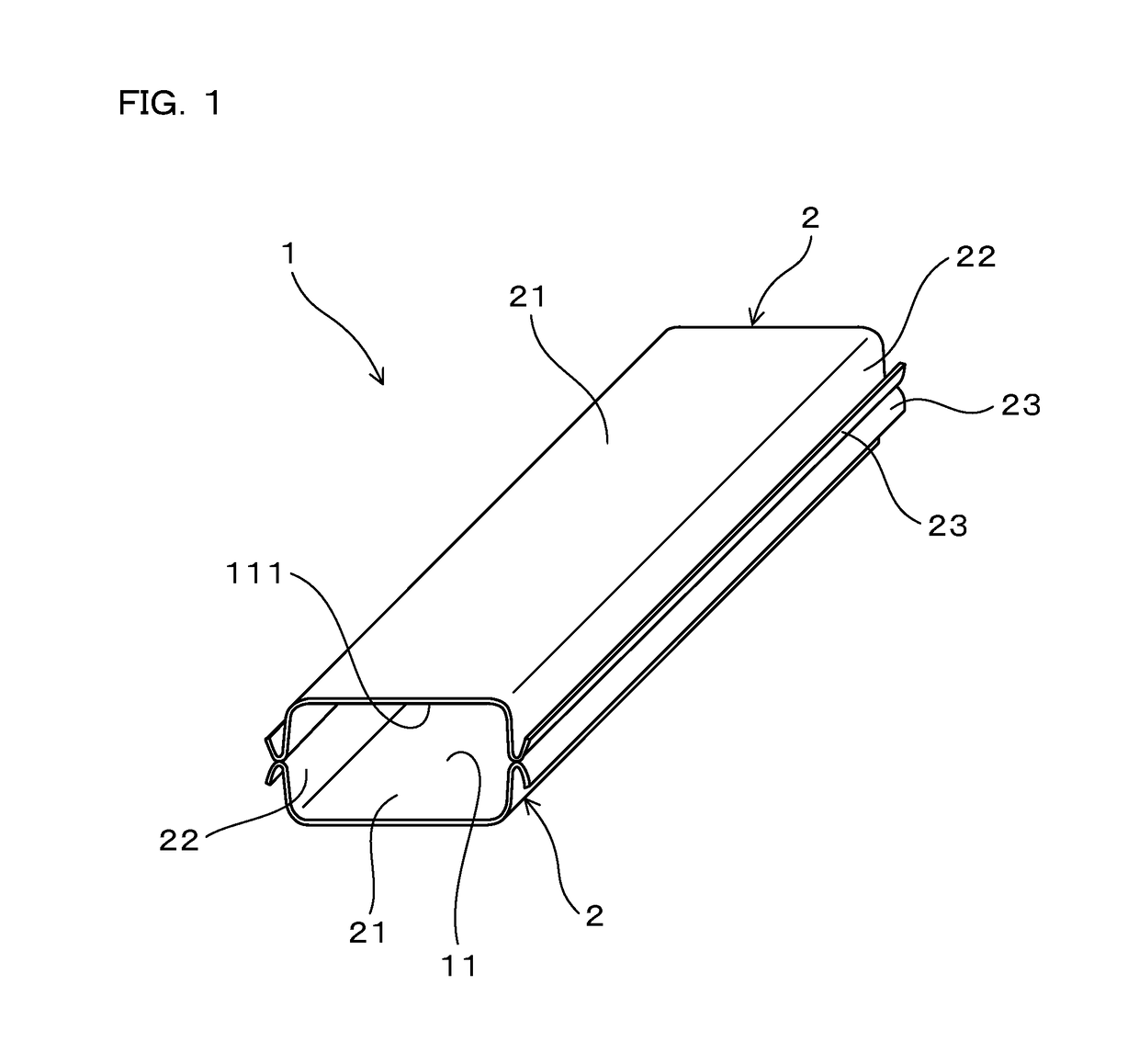
[0078]Working examples of the brazing method will be explained with reference to the drawings. An object to be processed 1 of the present example is constituted from two brazing sheets 2 as shown in FIGS. 1 and 2, and a tube-shaped hollow portion 11 surrounded by the two brazing sheets 2 is present. The brazing sheet 2 of the present example is a single-sided brazing sheet in which a filler metal layer B is clad onto one surface of a core layer C as shown in FIG. 2(a). Each brazing sheet 2 has a top wall 21, and a pair of side walls 22 that are formed by folding the top wall 21 at both ends thereof in the sheet width direction. The pair of side walls 22 extend from the ends of the top wall 21 toward the filler metal layer B side in the thickness direction of the top wall 21. In addition, at a tip end of each side wall 22, a flange part 23 is formed by folding back the brazing sheet 2 towards the top wall 21 side.

[0079]The two brazing sheets 2 are disposed such that the fill...

example 2

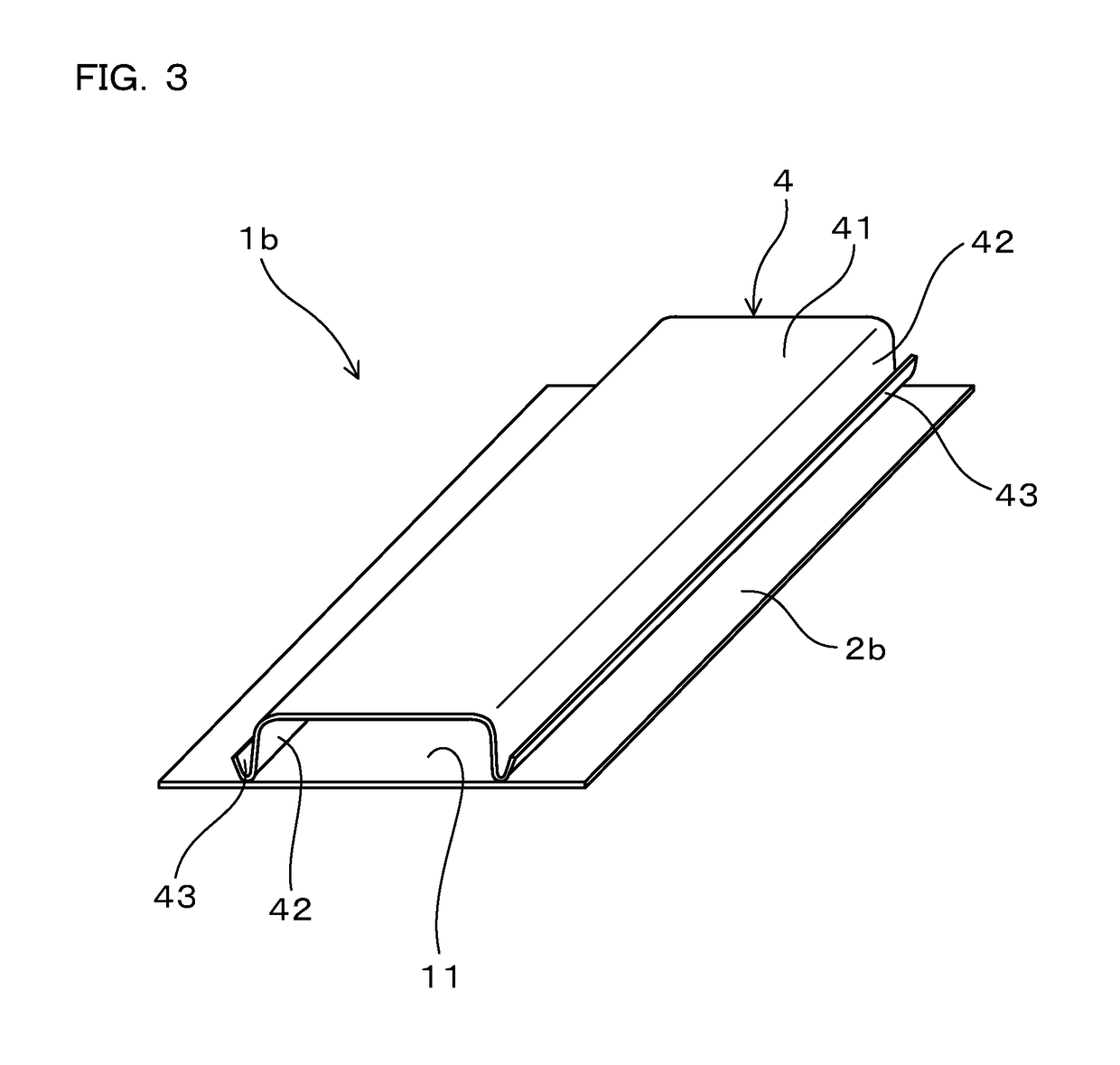
[0111]The present example is an example of the brazing method of an object to be processed 1b that includes another component other than the brazing sheet 2. The object to be processed 1b of the present example, as shown in FIGS. 3 and 4, was constituted from a planar brazing sheet 2b and an upper component 4 placed on the brazing sheet 2b, and there was a tube-shaped hollow portion 11 surrounded by the brazing sheet 2b and the upper component 4. It is noted that the reference numbers used in FIGS. 3 and 4 are the same as were used in Example 1 to indicate the same structural elements, etc. except as otherwise explained.

[0112]The upper component 4 was formed by folding an aluminum sheet of 0.4 mm thickness made of JIS A 3003 alloy, and had a similar shape to that of the brazing sheet 2 in Example 1. That is, as shown in FIGS. 3 and 4, the upper component 4 includes a top wall 41, a pair of side walls 42 that are formed by folding the top wall 41 at both ends thereof in the width dir...

example 3

[0120]The present example is an example of another configuration of the object to be processed 1 to which the brazing method is applicable. The brazing method can be applied to objects to be processed 1 of a variety of modes, provided that the object to be processed 1 is composed of aluminum material and has a hollow portion 11. FIGS. 5 to 7 show examples of such configurations of the objects to be processed 1 (1c, 1d, and 1e). It is noted that FIGS. 5 to 7 show the state in which brazing of the object to be processed 1 has been completed. The filler metal layer B in the brazing sheets 2 is melted by heating during the brazing and moves to an inner join part 12 and to an outer join part 13. For that reason, as shown in FIGS. 5 to 7, no filler metal layer B remains on the surface of the core layer C in the state in which brazing has been completed, except on the inner join part 12 and the outer join part 13.

[0121]For example, the object to be processed 1 may have an inner fin 5 inter...


PUM

PropertyMeasurementUnit
thermal decomposition temperatureaaaaaaaaaa
temperatureaaaaaaaaaa

Abstract

A hollow aluminum structure that will be brazed includes at least one brazing sheet having a filler metal layer clad onto a core layer. The core layer is composed of aluminum or an aluminum alloy containing less than 0.2 mass % Mg. The filler metal layer is composed of an aluminum alloy that contains Si: 4.0-13.0 mass % and Bi: 0.01-0.3 mass %, and further contains Li: 0.004-0.08 mass % and / or Be: 0.006-0.12 mass %, the filler metal layer containing less than 0.1 mass % Mg. The hollow aluminum structure is assembled such that the filler metal layer is present at locations that will form both an interior-facing brazed joint and an exterior-facing brazed joint. Then, flux is applied onto the filler metal layer at the location that will form the exterior brazed joint, and the hollow aluminum structure heated in an inert gas atmosphere to form the interior brazed joint and the exterior brazed joint.

Description

CROSS-REFERENCE[0001]This application is the US national stage of International Patent Application No. PCT / JP2015 / 082035 filed on Nov. 13, 2015, which claims priority to Japanese Patent Application 2014-250724 filed on Dec. 11, 2014TECHNICAL FIELD[0002]The present invention relates to a brazing method of aluminum material.BACKGROUND ART[0003]Having various advantages such as high thermal conductivity, lightweightness, etc., aluminum materials are widely used in heat exchangers and the like. For example, a heat exchanger mounted on an automobile includes components such as a tank, a tube and a fin, which are made of pure aluminum or an aluminum alloy, and these components are joined by brazing. Further, for brazing aluminum materials, a brazing sheet, on which a brazing filler material is clad at least on one side of an aluminum alloy sheet, is often used. Because the brazing sheet makes it possible to collectively braze a large number of components, the overall brazing process can b...

Claims


Application Information

Patent Timeline
Patent Type & Authority Patents(United States)
IPC IPC(8): B23K1/00B23K35/28B23K1/19B23K1/20B23K31/02B23K35/22C22C21/00B23K35/02C22C21/02F28F21/08F28F3/02F28F1/02B23K101/14
CPCB23K35/288B23K1/0012B23K1/19B23K1/20B23K1/203B23K1/206B23K31/02B23K35/0238B23K35/22B23K35/28B23K35/286C22C21/00C22C21/02F28F1/02F28F3/025F28F21/084B23K1/00F28F2275/045B23K2101/14
Inventor YANAGAWA, YUTAKAITOH, YASUNAGAYAMAYOSHI, TOMOKI
Owner FURUKAWA SKY ALUMINUM CORP
Learn More