
System and method for transferring electrical power between grid and vehicle

a technology of electrical power transmission and grid, applied in the direction of electric propulsion mounting, battery/fuel cell control arrangement, instruments, etc., can solve the problems of no longer supporting distributed generation, the cost of recharging the vehicle in a static pricing scheme would outweigh the savings from pushing back, etc., to reduce the amount of load on the grid, increase the available power, and improve the effect of efficiency and rapid respons

Inactive Publication Date: 2009-01-29
ITRON NETWORKED SOLUTIONS INC
View PDF25 Cites 296 Cited by
  • Summary
  • Abstract
  • Description
  • Claims
  • Application Information

AI Technical Summary

Benefits of technology

[0013]3. Super-peak power discharging to help decrease the danger of a brownout / blackout event
[0015]The controls for such a system will ideally come from the electric utility. This way, compensation can be given for vehicles during the times they are regulating power. Also, the utility is in the best position or organize and optimize the mitigation of brownout and blackouts by cycling the available vehicles similar to air-conditioner cycling in areas with load shedding to reduce peak demand. This way the available power is not all used up after a few short hours if there is still a shortage on the grid.
[0029]The more control and information the utility exerts and provides, the more effectively the grid is utilized. Cycling charging among a large group of cars ensures that a steady load is present during the night and other popular recharging times so the grid is not overwhelmed. Draining the batteries in a similar manner will allow the utilities to ensure a longer time period during which vehicle power is available, so as not to completely drain the available sources of emergency peak power.
[0035]Knowing the vehicle type and power plant information allows the utility or aggregator to selectively allow charging / generation to maximize effectiveness of its load limiting and power reliability programs. The utility may allow regulation during all hours, or only during times when ACE is outside the desired range specified by the utility.
[0038]The disclosed system will buffer the home and vehicle from the grid in the event of a severe brownout or blackout, allowing the home to receive electricity from the vehicle to provide power. Utilities with smart meters can assist with recovering from energy emergencies by using the battery-powered AMI meters to block electrical flow to homes affected by the brownout / blackout in order to lower the amount of load on the grid. Residences and locations with EVs, PHEVs, and FCVs can then be brought back on the grid to help increase the available power, and then homes without generation means can be brought back online without fear of sending the grid back into chaos by turning on all residences at the same time.
[0039]In this scenario, the disclosed system protects the vehicle(s) in an individual residence by separating them from the problems on the grid. This protects the household electronics and the vehicle. Most inverters will shut off when the electrical signal it is trying to match is altered or lost, but the ability for vehicles to help recover from the problem is lost in this case. Separating the vehicle from the grid until it is safe to allow it to help power back on the local grid is both an efficient and rapid response to help get power back to the utility customers.

Problems solved by technology

This has several flaws since the vehicles are not 100% efficient, and the cost to recharge the vehicle in a static pricing scheme would outweigh the savings from pushing it back onto the grid.
Since the batteries charge primarily from the grid (some have solar or regenerative means while driving), when their batteries run out, they can no longer support distributed generation.
Instead of purchasing expensive power from a neighboring utility or running out of available power, the utility could tap into the energy from vehicles.
This scenario typically happens only for a short duration only a few times a year, and the money earned from providing power to the grid would surely exceed the costs for the customer to provide it.
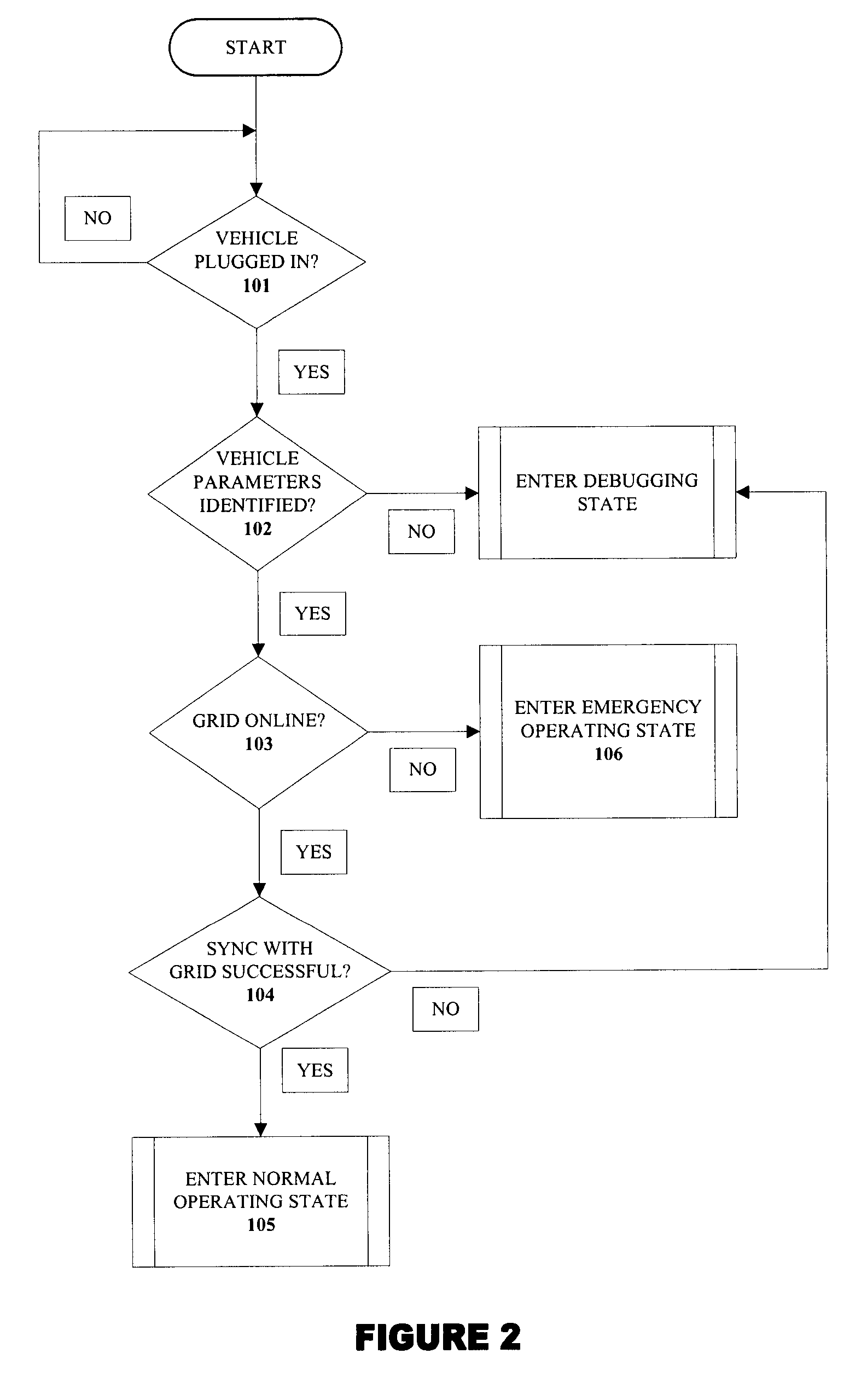
In the event of a blackout, the vehicle should not try to re-energize the grid by itself, because it probably cannot and may damage household wiring, the electric meter, or the car's electrical system.

Method used


Image

  • System and method for transferring electrical power between grid and vehicle
  • System and method for transferring electrical power between grid and vehicle
  • System and method for transferring electrical power between grid and vehicle

Examples


Embodiment Construction

[0046]The present invention discloses a system for transferring electrical power between a grid and at least one vehicle. The system further provides an electrical isolation between the vehicle, the grid and a building in case of a brownout or a blackout event. The system also facilitates in providing electrical power to the building from the vehicle. In one embodiment of the invention, at least one battery is used as the means for storing electrical power in the vehicle. However, other electrical power storage devices can also be used, without limiting the scope of the invention.

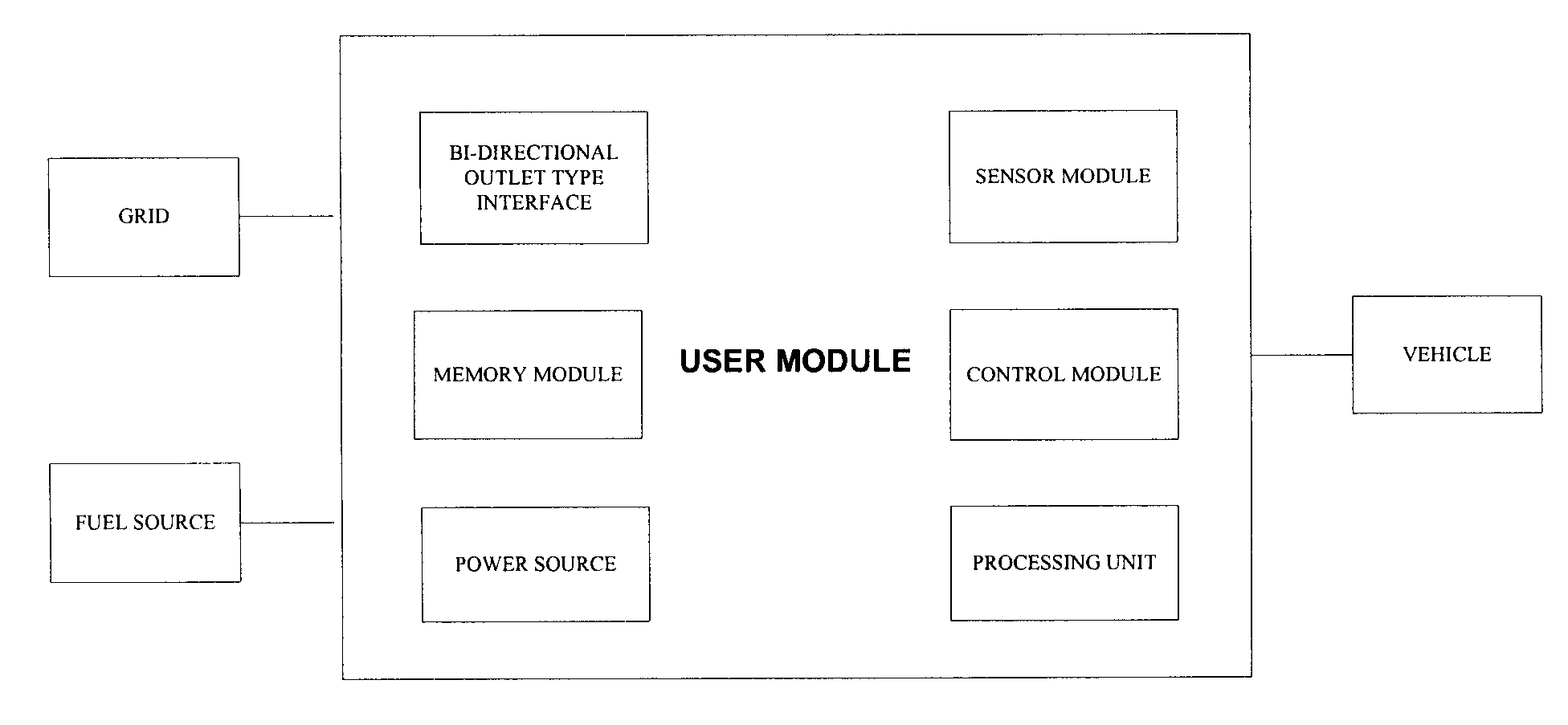
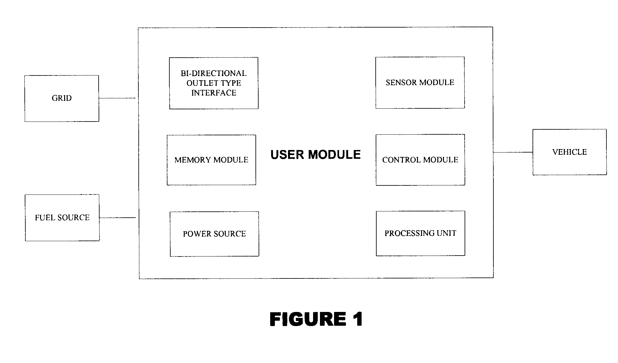
[0047]The system comprises of a user module connected to the grid and to the vehicle via a communication network. The user module is further connected to a fuel source. The communication network comprises of Communication Over Power Line (COPL), Bluetooth, IEEE 802.15.4, ZigBee, cellular wireless network or IP based computer network. The communication network uses protocols such as, for example, BACnet, Lon...


PUM


Abstract

The present invention discloses a system for transferring electrical power between a grid and at least one vehicle. The vehicle can be Battery Electric Vehicle (BEV), Plug-in Hybrid Electric Vehicle (PHEV) or Fuel Cell Vehicle (FCV). The type of vehicle will be recognized and controlled by the system to support demand response and supply side energy management. Vehicle recognition can be carried out by load signature analysis, power factor measurement or RFID techniques. In an embodiment of the invention, the grid is a Smart Grid. The present invention also discloses a method for facilitating electrical power transfer between the grid and the vehicle.

Description

BACKGROUND OF THE INVENTION[0001]Battery electric vehicles (BEVs), Plug-In Hybrid Electric Vehicles (PHEVs), and Fuel Cell Vehicles (FCVS) can provide many positive functions to the electrical utility grid and its customers.[0002]The most basic example involves net metering, in which electricity can flow both directions in a residence, and the customer is billed only for the net electricity consumed during the billing period. In this case, vehicles can be programmed to push electricity back onto the electrical grid to help reduce the total electricity consumed in the residence.[0003]This has several flaws since the vehicles are not 100% efficient, and the cost to recharge the vehicle in a static pricing scheme would outweigh the savings from pushing it back onto the grid.[0004]This leads to a more advanced scenario, wherein the vehicles push electricity on the grid in variable pricing areas only when the money earned will be more than the cost to recharge the battery, as well as pay...

Claims


Application Information

Patent Timeline
Patent Type & Authority Applications(United States)
IPC IPC(8): G06Q50/00B60K1/00G08G1/123H02J7/00
CPCB60L11/1816B60L11/1838B60L11/184B60L11/1846B60L11/1848B60L11/1887Y04S30/14Y02T90/128Y02T90/14Y02T90/163Y02T90/169Y02T90/34Y02T90/121Y02T10/7072B60L53/14B60L53/64B60L53/65B60L53/665B60L58/40B60L53/68Y02T90/167Y02T90/12Y02T90/16Y02T10/70Y04S30/12B60L55/00Y02T90/40
Inventor BOGOLEA, BRADLEY D.BOYLE, PATRICK J.
Owner ITRON NETWORKED SOLUTIONS INC
Learn More