Switch and device using the switch

Active Publication Date: 2013-03-12
TYCO ELECTRONICS RAYCHEM KK
View PDF14 Cites 2 Cited by
  • Summary
  • Abstract
  • Description
  • Claims
  • Application Information

AI Technical Summary

Benefits of technology

[0022]According to the present invention, there is provided a novel switch having a function of overcurrent protection. When the switch of the present invention is applied to an electric/electronic device, advantages of a smaller space, a fewer number of components, simplification of producing steps, improved safety and so on are attained in comparison with a case of using the conventional gen

Problems solved by technology

In a case of the conventional general switch, since it is used in combination with a current fuse, a design of an electric/electronic device is limited by requiring a space for locating the current fuse in its housing.
In addition to the necessity of the current fuse and its accessories (such as a cable), there is an additional disadvantage of requiring a step of soldering for electrically connecting the current fuse.
Furthermore, since the current fuse generally exposes a lead portion thereof, a risk of short circuit caused by any trouble would be expected.
Further, there is also a disad

Method used


Image

  • Switch and device using the switch
  • Switch and device using the switch
  • Switch and device using the switch

Examples


embodiment 1

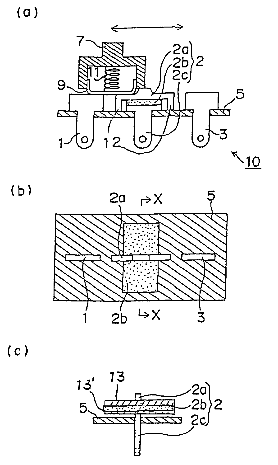
[0039]An exemplary slide switch to which the present invention applied is described with reference to FIGS. 1(a) to (c). In general, a slide switch means a switch for opening and closing a path between contacts by sliding operation of an operating part. In this embodiment, an example of a single pole double throw-type slide switch which is utilizable for switching electric circuits is described.

[0040]As shown in FIGS. 1 (a) to (c), the slide switch 10 of this embodiment has a conductive movable member 9 and three terminals 1, 2 and 3. The terminals 1, 2 and 3 have a fixed contact and respectively fixed to a substrate 5. On the other hand, the movable member 9 has a movable contact, and the movable member 9, an operating part 7 and a spring 11 consist a movable component. As shown in FIG. 1 (a), the movable member 9 fits with a recess of the operating part 7 while being able to move up and down, and is pressed by an elastic force of the spring 11 in the recess against the terminals 1...

embodiment 2

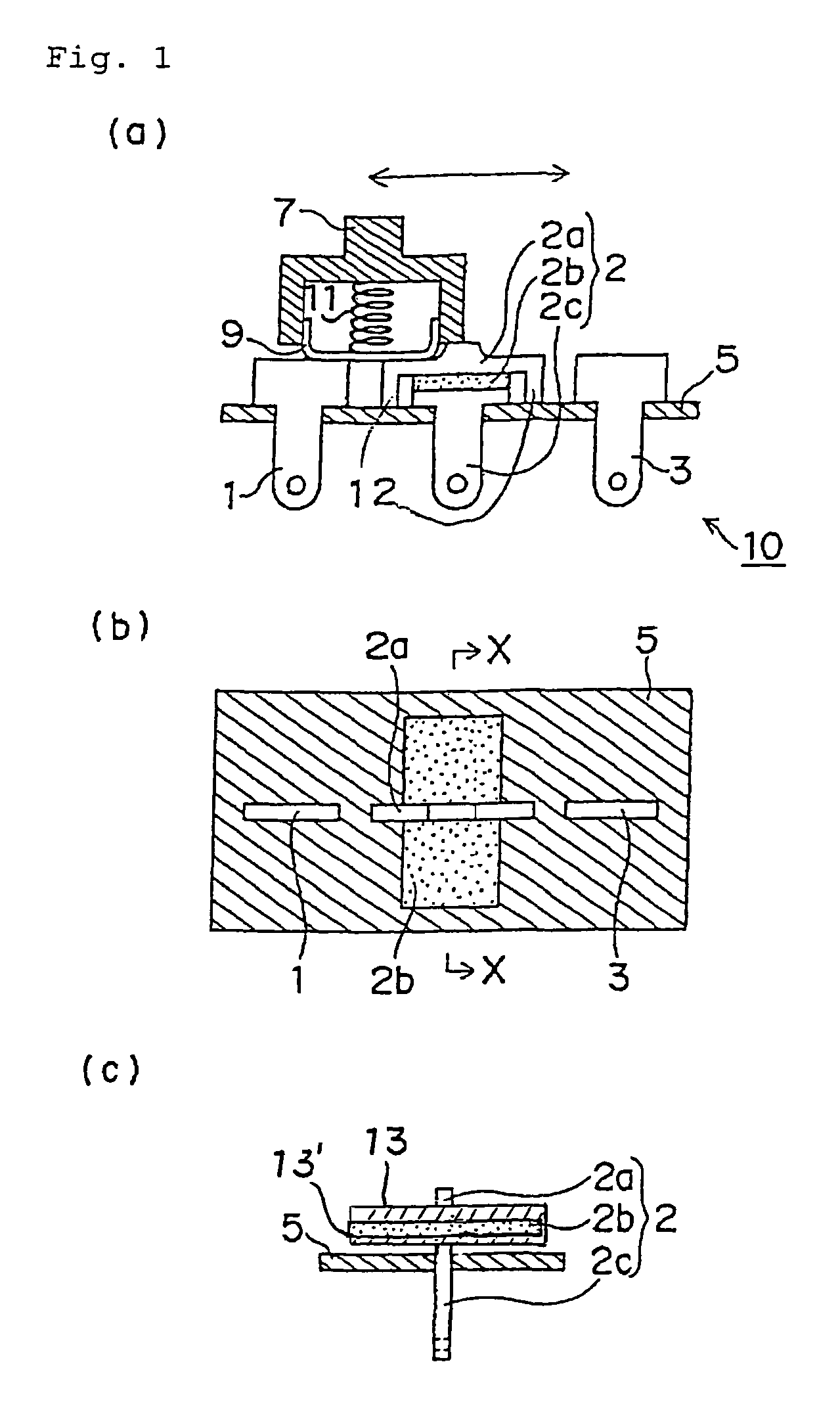
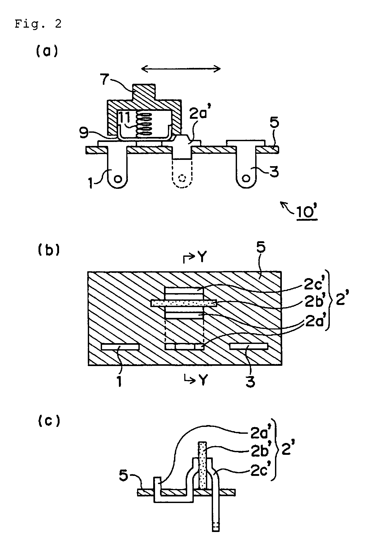
[0057]Another exemplary slide switch to which the present invention applied is described with reference to FIGS. 2 (a) to (c). This embodiment is modified one of the slide switch of the above Embodiment 1.

[0058]The slide switch 10′ of this embodiment has a construction similar to the slide switch 10 of the above Embodiment 1, excepting the structure of a terminal 2′. In FIGS. 2 (a) to (c), members or elements corresponding to those shown in FIGS. 1 (a) to (c) are shown with similar numerals. The slide switch 10′ of this embodiment is similar to the slide switch 10 of the Embodiment 1, unless otherwise specified hereinafter.

[0059]The terminal 2′ is composed of a contact part 2a′, a connect part 2c′, and a PTC member 2b′ sandwiched therebetween. More specifically, the contact part 2a′ runs along the substrate 5, and the PTC member 2b′ stands on the substrate 5 between the contact part 2a′ and the connect part 2c′ so that the opposed surfaces of the PTC member 2b′ are substantially ver...

embodiment 3

[0062]An exemplary toggle switch to which the present invention is applied is described with reference to FIGS. 3 (a) and (b). In general, a toggle switch means a switch for opening and closing a path between contacts by changing operation of an operating part between upright and tilted positions. In this embodiment, an example of a single pole double throw-type toggle switch which is utilizable for switching electric circuits and ON-OFF of a power supply is described.

[0063]As shown in FIGS. 3 (a) and (b), the toggle switch 20 of this embodiment has a conductive movable member 29 and three terminals 21, 22 and 23. The terminals 21, 22 and 23 have a fixed contact and respectively fixed to a substrate 25. On the other hand, the movable member 29 has a movable contact, the movable member 29, an operating part 27, a spring 31, a post 33, and a converting element 35 consist a movable component. As shown in the drawings, the movable member 29 is in the form in which two curved parts are c...


PUM


Abstract

There is provided a novel switch having a function of overcurrent protection. In a switch comprising a conductive movable member (9) and at least two terminals (1, 2, 3) and being switchable by mechanically moving the movable member (9) between a state in which the movable member (9) contacts with the two terminals (1, 2) simultaneously and a state in which the movable member (9) is apart from either one (1) of the two terminals (1, 2), at least one (2) of the two terminals (1, 2) is separated into a conductive contact part (2a) for contacting with the movable member (9) and a conductive connect part (2b) for being electrically connected with an external element (not shown), and a PTC member (2b) is located between the contact part (2a) and the connect part (2c). The PTC member (2b) may be a PTC element having a PTC material layer and a pair of conductive material layers each located on opposed surfaces of the PTC material layer.

Description

TECHNICAL FIELD OF THE INVENTION[0001]The present invention relates to a switch used for various electric and / or electronic devices and activated by a mechanical switching operation (hereinafter simply referred to as a “switch”).BACKGROUND OF THE INVENTION[0002]In various electric / electronic devices, a switch activated by a mechanical switching operation is used to control, for example, switching of ON-OFF of a power supply and / or switching of electric circuits. It is known that such switch includes, for example, a slide switch, a toggle switch, a rotary switch, a push switch, a rocker switch (or a tumbler switch) and so on.[0003]Conventionally, such switch is generally used in combination with a current fuse in order to improve safety of the electric / electronic device by protecting a load of the electric circuit from overcurrent (hereinafter such switch without a function of protection is referred to as the conventional general switch). For example, in an electric circuit of electr...

Claims


Application Information

Patent Timeline
IPC IPC(8): H01H15/02H01H1/58H01H9/02H01H15/04H01H23/08H01H23/24H01H81/02
CPCH01H81/02H01H9/0271H01H15/04H01H2033/163H01H23/08
Inventor SUZUKI, KATSUAKI
Owner TYCO ELECTRONICS RAYCHEM KK
Why Eureka
Try Eureka