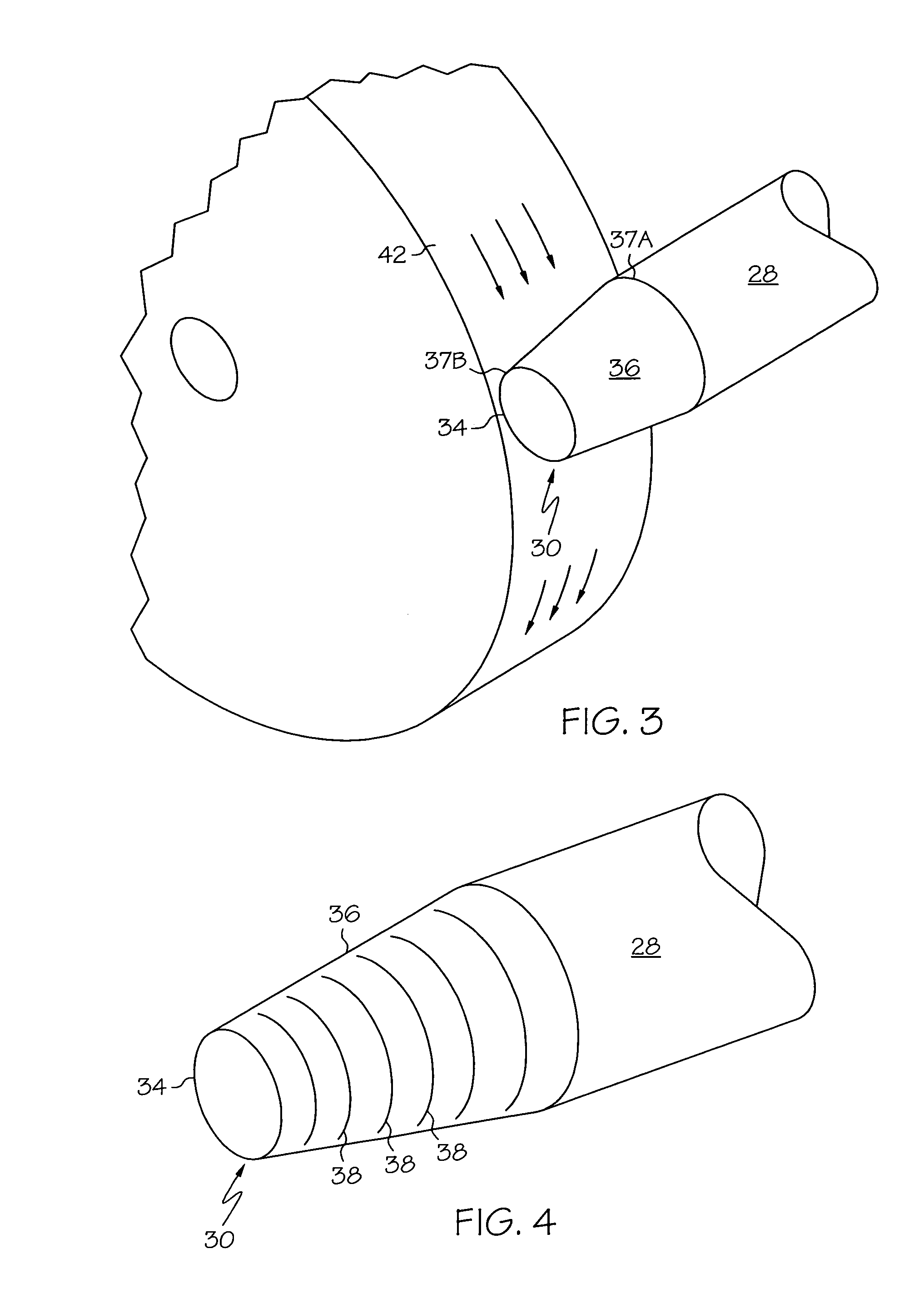
[0008]The present invention is directed to a tapered dispense tip
grinding method, and a dispense tip processed according to such a method, that overcome the aforementioned limitations associated with conventional techniques. In the present invention, the tip is presented to the
grinding wheel in a longitudinal orientation—the longitudinal axis of the neck of the tip is substantially aligned with the direction of movement of the
grinding wheel. In this manner, the taper is formed without the radial rings of conventional techniques, thereby providing a tip with further-reduced
surface tension and therefore increased dispensing precision capability.
[0009]In a second aspect, the present invention is directed to an
electropolishing technique whereby a beveled tip is electropolished to further buff, or remove,
tool marks generated during bevel formation. In this manner, burrs and pits are removed from the surfaces of the tip. This aspect is applicable to treatment of both conventional laterally-ground and the inventive longitudinally-ground tapered tips.
Electroplating may further be applied to external and internal tip surfaces to enhance surface
lubricity.
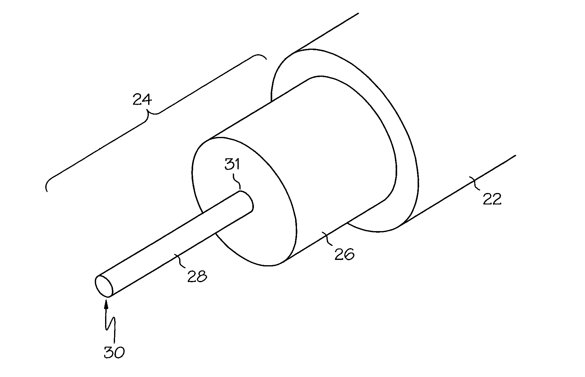
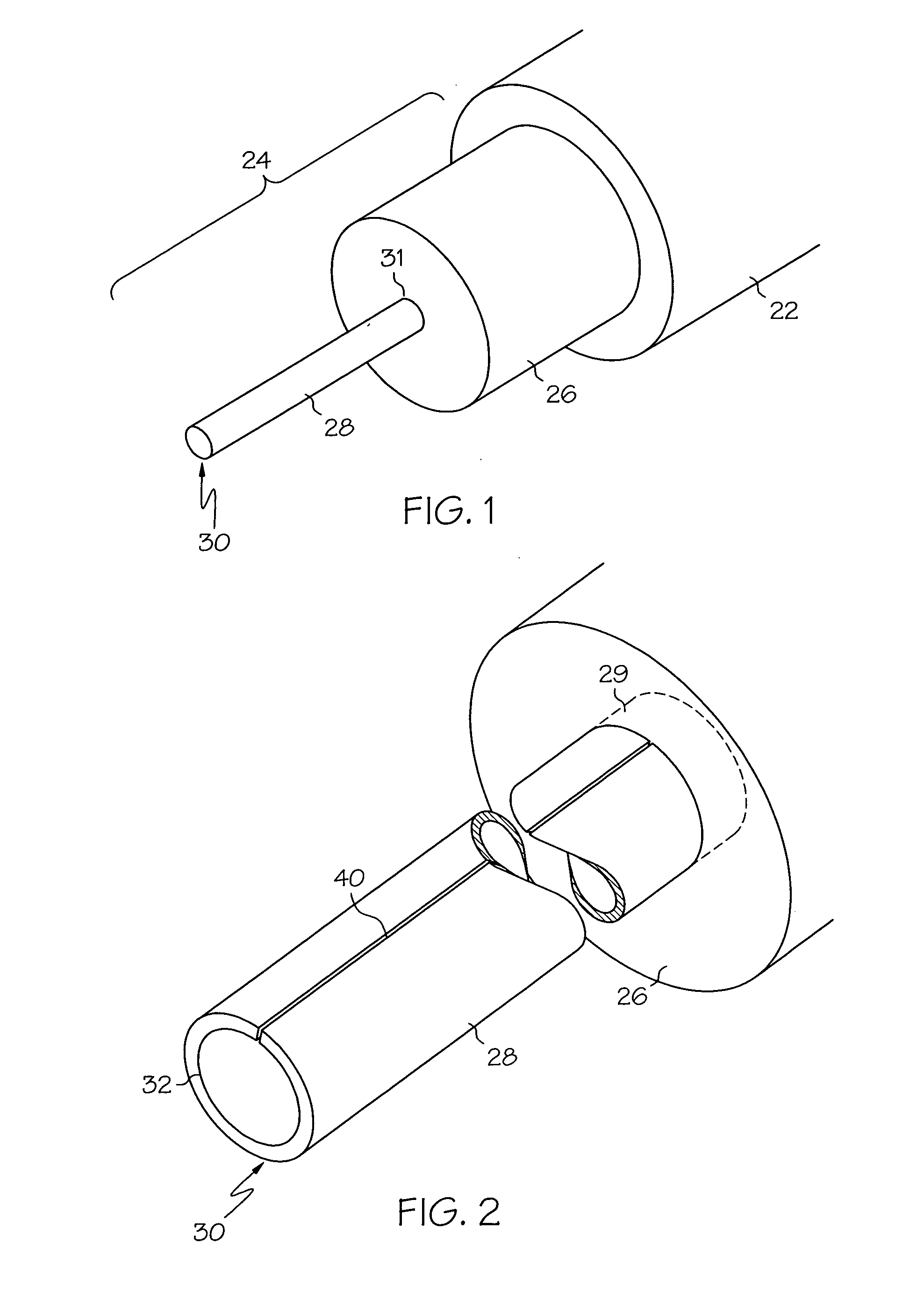
[0010]In a third aspect, the present invention is directed to a dispense tip formed in a
solid unitary piece, machined from stock. By
machining the neck opening, potential inner collapse of the neck due to rolling as in prior configurations is avoided. Furthermore, alignment of the neck with the body of the tip is unnecessary and complicated
assembly procedures are thereby avoided. The unitary tips further offer the
advantage of a robust neck, avoiding the need for bonding of the neck to an alignment foot. Because of the added robustness, the unitary tips are more amenable to deployment with longer-length necks than conventional configurations.
[0011]In a preferred embodiment of the third aspect, the neck is of a first inner diameter along a majority of its length, and of a second inner diameter proximal to the opening, the first inner diameter being greater than the second inner diameter. This configuration allows for delivery of the dispensed fluid to the opening at a relatively low pressure, as compared to conventional tips having a single, narrow diameter over their lengths, and is especially attractive to dispensing applications that require smaller diameter tips.
[0015]In a fourth aspect, the present invention is directed to a cleaning tool adapted for cleaning the inner surfaces of the neck of the dispense tip. The cleaning tool includes an elongated body that serves as a
handle during a cleaning operation, and a sharpened
shovel adapted to interface with, and shaped to correspond with, the tapered inner diameter of the tip neck. The
shovel is located on a bevel, the bevel having an angle substantially similar to the neck taper to allow the
shovel to access the tapered portion of the neck. Optional
drill flutes may be formed on the cleaning tool body for removing a bulk of the material from the inner surface during a cleaning operation. In this manner, buildup of hardened material is avoided, and dispense tip lifetime is extended.
[0016]In a fifth aspect, the present invention is further directed to a cleaning kit for cleaning dispense tips configured in accordance with the present invention, thereby extending the useful lifetime of the dispense tips. The kit is preferably enclosed in a plastic, non-scratch compartmentalized receptacle, and includes a pin-
vise,
magnet,
syringe and
plunger,
magnifying glass, cleaning wires, and cleaning tools. The pin
vise is adapted to secure the miniature wires and drills during a cleaning operation. The
magnet is helpful for locating the wires and drills on a work surface, for example by using a sweeping motion of the
magnet over the surface. The
syringe and
plunger are provided for flushing out the dispense tips following cleaning with the wires and fluted
drill bits.
Alcohol is a preferred liquid for the flushing operation. A
magnifying glass helps with inspection of the dispense tips during, and following, cleaning. Cleaning wires include cleaning wires with tapered ends for eased
insertion into the dispense tips. Cleaning tools include fluted
drill bits for coarse cleaning of the inner necks, a shoveled cleaning tool, described above, for cleaning the inner taper of unitary dispense tips, and a liner
insertion tool, described above, for inserting liners into the unitary dispense tips.

