
Apparatus for removing and erecting a folding-box blank
a technology for removing and erecting magazines, which is applied in the field of removing a folding box blank from a magazine, can solve the problems of occupying a relatively large amount of space and requiring a relatively long period of time for the removal and erecting operations
- Summary
- Abstract
- Description
- Claims
- Application Information
AI Technical Summary
Benefits of technology
Problems solved by technology
Method used
Image

Examples
Embodiment Construction
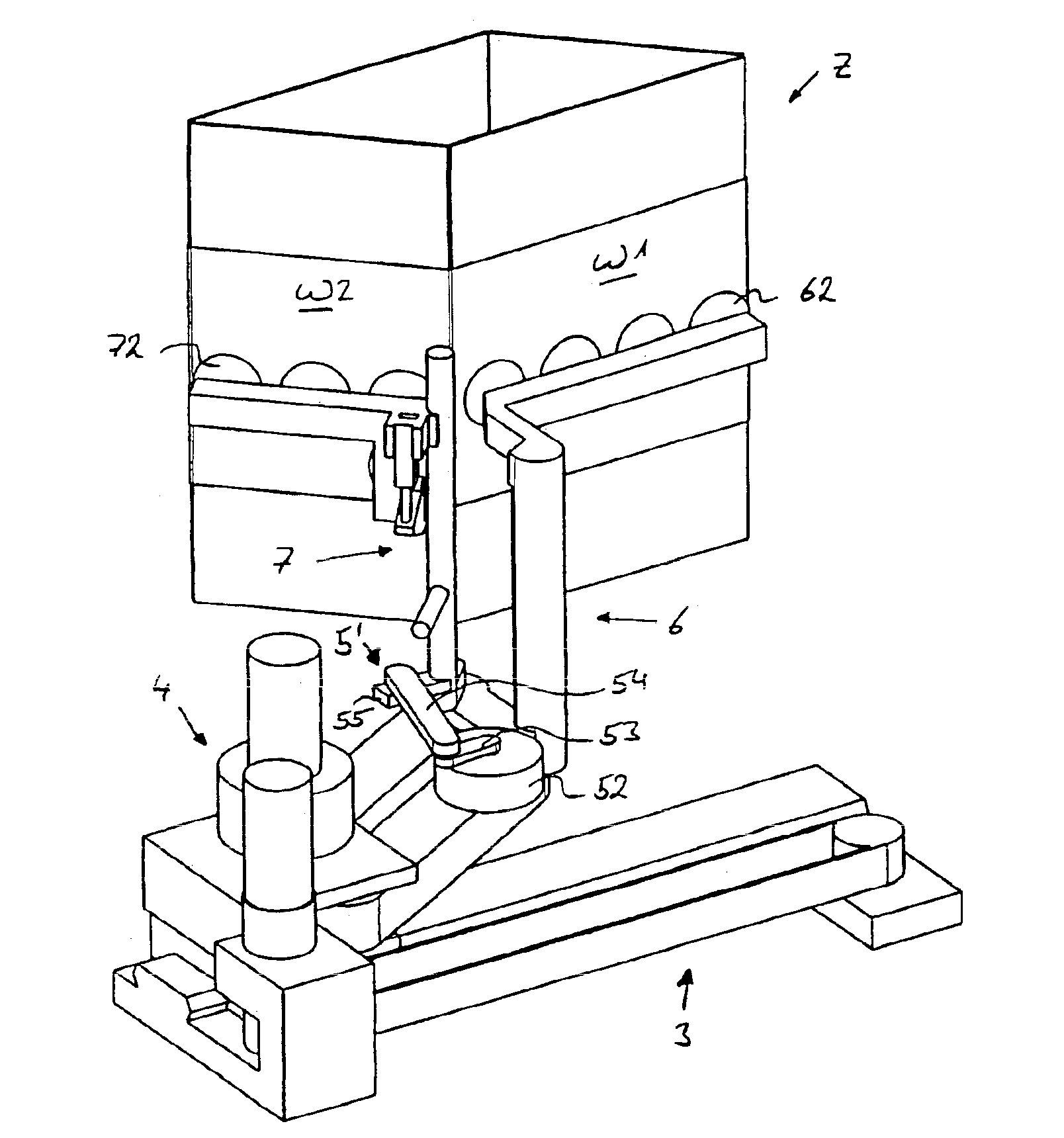
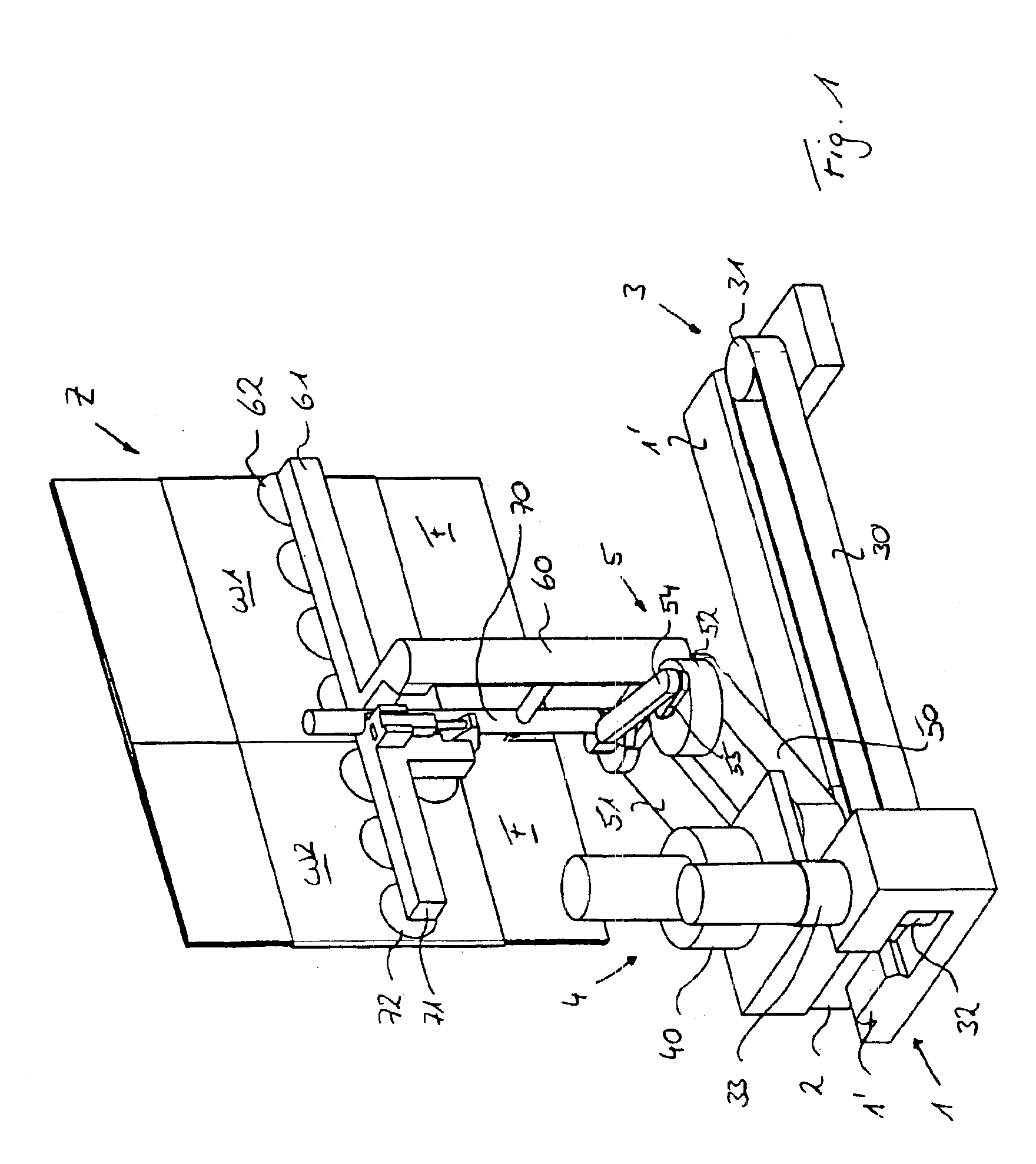
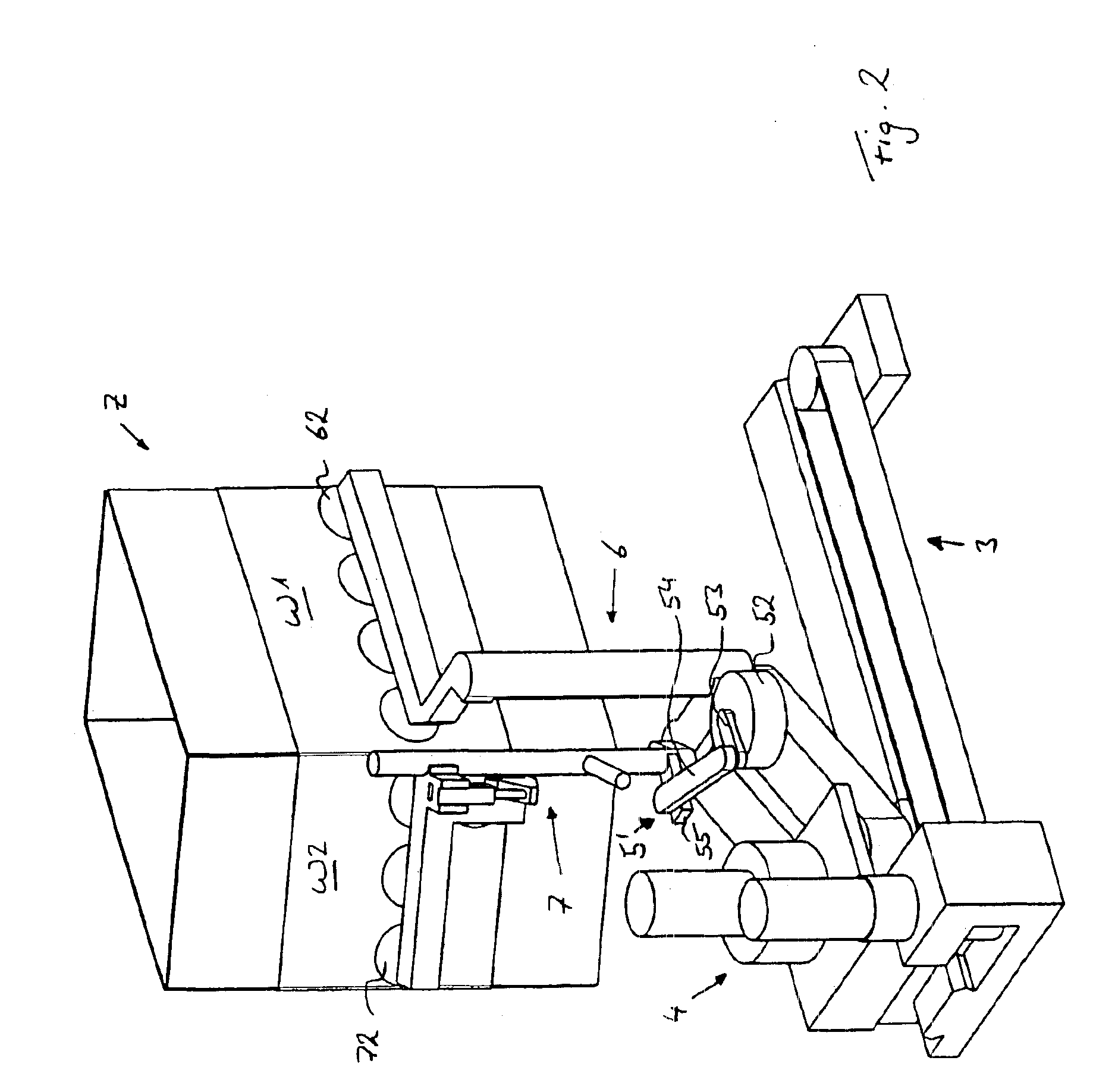
[0018]FIG. 1 illustrates an apparatus according to the invention. The apparatus has a base 1 with a guide track 1′. A carriage or sled 2 is arranged on the guide track 1′ such that it can be displaced in a translatory manner. The translatory drive means 3 provided here is a belt drive with a belt 30 which runs parallel to the guide track 1′ and on which the carriage 2 is fastened. The belt 30 runs around a deflecting roller 31 and a drive roller 32, the latter being driven by means of a first motor 33.
[0019]A parallelogram linkage 5 is arranged in a pivotable manner on the carriage 2. Its pivot axis here preferably runs perpendicularly to the plane of the guide track 1′. A pivoting-drive means 4 with a second motor 40 has been provided for this purpose, said motor transmitting a pivoting movement to a first end of the parallelogram linkage 5, this end being arranged on the carriage 2.
[0020]Arranged at a second, free end of the parallelogram linkage 5, on in each case one rod or bar ...
PUM
 Abstract
Description
Claims
Application Information