Tool for installing nail-pin anchors and anchor bolts

a technology for installing nails and anchor bolts, which is applied in the direction of nail dispensers, manufacturing tools, paper/cardboard containers, etc., can solve the problems of damage to the anchor dome, inefficiency and even ineffective tools used for driving and setting nails-pin anchors, and inefficient and even ineffective tools

Inactive Publication Date: 2005-07-12
MATRIX TOOL
View PDF13 Cites 29 Cited by
  • Summary
  • Abstract
  • Description
  • Claims
  • Application Information

AI Technical Summary

Benefits of technology

[0004]The present invention provides a tool for installing nail-pin anchors and anchor bolts which overcomes the problems of the prior art. The tool, made of steel parts, is designed so that novices can use it. The tool is safe and comfortable to use. It eliminates the need to switch from one tool to another, thereby saving time. It completely eliminates the need to use hand-held hammers or mallets.
[0005]Using a rotary hammer drill with a masonry drill bit, the installer drills a hole in the concrete or masonry and inserts the end of a nail-pin anchor or anchor bolt into the hole. He then picks up the tool (with knurled outer surfaces to improve handing) and slides the socket end of the tool over the masonry drill bit until the tool rests against the drill's domed foundation. Then he rotates the tool a quarter of a turn (90°), temporarily locking the tool to the masonry drill bit. A spring clip can be used to provide an additional means of holding the tool onto the bit. As a result, the installer can use the tool to install anchors at any angle, including upside-down. Holding the rotary hammer drill with one hand, the installer grips the tool with the other hand and places the milled end against the anchor. The tool of the present invention can have a concave milled tip which fits over the dome of a nail-pin anchor sleeve. The installer squeezes the trigger of the drill, and the percussive force of the drill causes the tool to seat the dome of the anchor against the surface of the concrete and, simultaneously, set the nail into the sleeve. For anchors with threads, the tool will squarely impact the strike end of the stem of the threaded anchor and drive it in without bending it; the nut can then be easily threaded onto the stem.
[0006]The tool can be used without damaging the nail-pin anchors, the anchor bolts, or the surfaces of the objects being anchored. The installer is able to stay completely focused on installing each anchor. Finally, installation of each anchor takes considerably less time than does the process using presently-available tools.

Problems solved by technology

Presently, the tools used for driving and setting a nail-pin anchor can be inefficient and even ineffective.
The tools presently used can be difficult to align in order to hammer the anchor sleeve into the hole, and they may damage the dome of the anchor, which is often made from soft metal.
Having to then switch to a different tool for driving the nail requires re-alignment, wasting time and causing the installer to lose his focus.
When dozens of anchors must be set, the expenditure of time can be substantial.
When used to drive in the nail, the presently-available tools may cause the nail to bend to one side and can even cause the nail head to chip off.
Nail-pin anchors may not be properly set, resulting in a poor result, both structurally and cosmetically.
The same problem arises when an installer uses a mallet or hammer to drive in the threaded bolt of an anchor bolt, or any other kind of anchor with a shaft.
If the anchor setter improperly impacts the setting end of the threaded anchor, the stem may bend, making it difficult to thread the nut onto the stem.
In hard-to-reach places, the installer using presently-available tools has little room to hammer in either a nail-pin anchor or an anchor bolt; in such circumstances, the anchor is even more likely to fail.

Method used


Image

  • Tool for installing nail-pin anchors and anchor bolts
  • Tool for installing nail-pin anchors and anchor bolts
  • Tool for installing nail-pin anchors and anchor bolts

Examples


Embodiment Construction

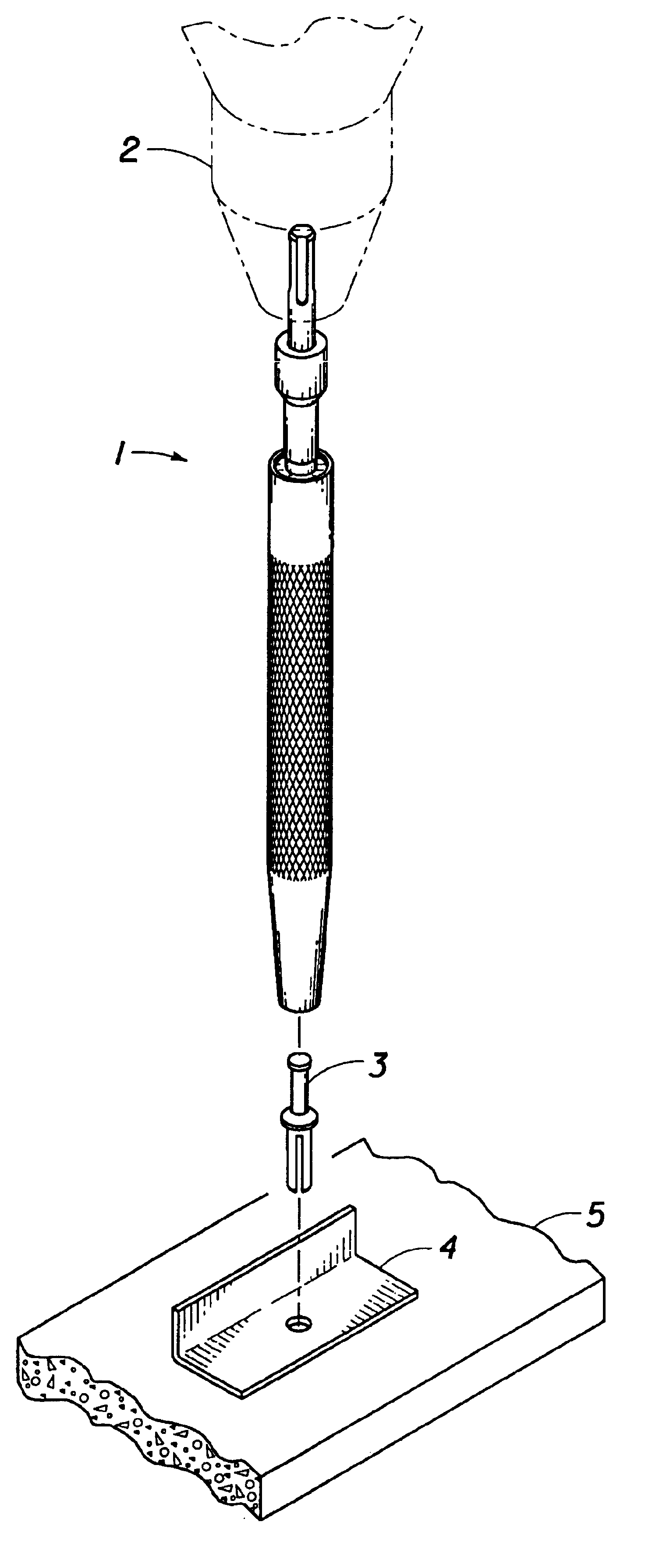
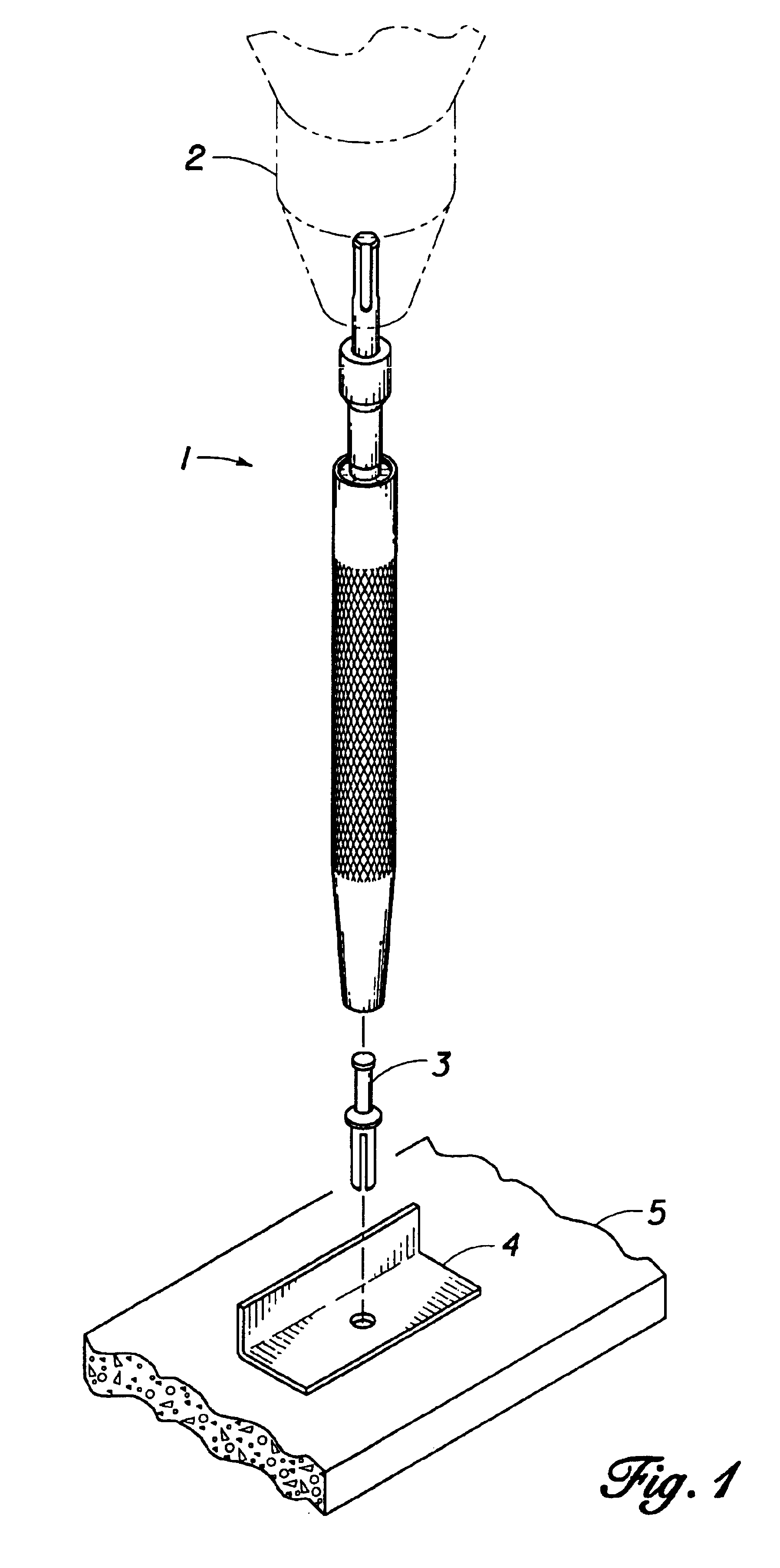
[0023]As shown in FIG. 1, the anchor setting tool 1 of the present invention is used with a rotary hammer drill 2 to drive a nail-pin anchor 3 through a hole in an angle iron bracket 4 and into a drilled hole in a concrete block 5 and set it.

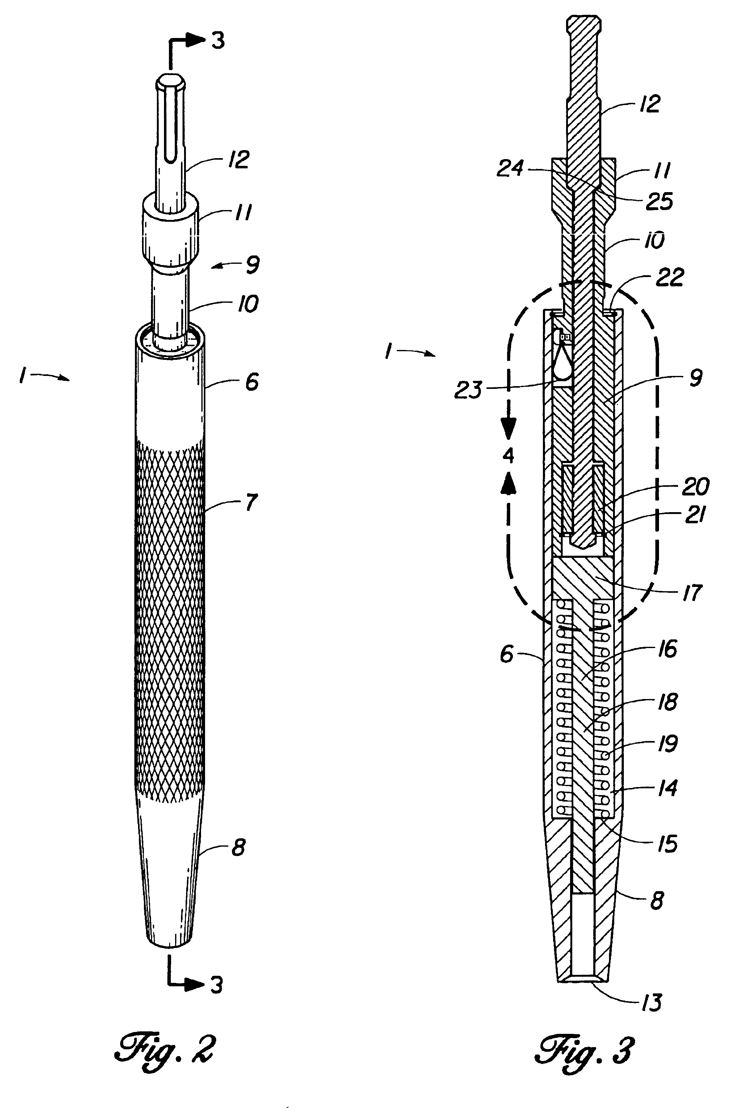
[0024]FIG. 2 shows the assembled anchor setting tool 1. The body 6, which serves as the hand grip, is made from a hard metal such as 1 inch Barstock grade metal (such as 4140). The body 6 has knurls 7 on its surface to prevent slippage of the tool 1, as well as a tapered end 8, so that the tool 1 can be used to set anchors in a tight area, such as a channel. Inserted into the upper end of the body 1 is a ram 9 having a stem 10 and a socket end 11, into which has been inserted a masonry drill bit 12.

[0025]The sectional view in FIG. 3 shows the elements cooperating inside the body 6 of the tool 1. The tapered end 8 optionally can be milled with a concave tip 13 to fit over the dome of a nail-pin anchor or rivet. Alternatively, the tip 13 can be fl...


PUM

PropertyMeasurementUnit
percussive forceaaaaaaaaaa
shapeaaaaaaaaaa
wasting timeaaaaaaaaaa

Abstract

A tool for driving and setting nail-pin anchors and anchor bolts into concrete, the tool using the percussive action of a rotary hammer drill. The tool comprises a body member with a spring, a driver, and a ram inserted into the body member's bore. After a hole is drilled for insertion of the anchor, the masonry drill bit of the rotary hammer drill is slid inside the bore of the ram and temporarily locked to the tool. The rotary hammer drill is activated, and the drill bit turns inside the ram without affecting the body member or the anchor. Instead, the percussive force of the rotary hammer drill transfers its impact to the ram and the driver, which impacts the nail of the nail-pin anchor, or the stem of the anchor bolt, setting it into the concrete. A keyed bearing can be installed inside a sleeve of the ram in order to protect the tip of the masonry drill bit from shearing.

Description

FIELD OF THE INVENTION[0001]The present invention relates to a tool for installing nail-pin anchors and anchor bolts, in connection with a rotary hammer drill with a masonry drill bit.BACKGROUND OF THE INVENTION[0002]Nail-pin anchors and anchor bolts (sometimes called “quick bolts”) are widely used in the construction industry. A nail-pin anchor has an anchor sleeve topped by a convex-shaped crown or dome. A nail is inserted into the sleeve through a hole in the dome. A hole is drilled in the concrete or brickwork. The anchor sleeve is inserted through a mounting hole in a structural piece (or through an opening in an angle iron bracket, etc.) and manually hammered into the hole in the concrete. Finally, the nail is driven into the sleeve, forming a wedge and setting the anchor. When a concrete or masonry anchor bolt with threads is installed, the threaded bolt is manually hammered into a hole in concrete. Then a nut is threaded onto the stem of the anchor.[0003]Presently, the tools...

Claims


Application Information

Patent Timeline
Patent Type & Authority Patents(United States)
IPC IPC(8): B25B31/00
CPCB25B31/00Y10T29/5393
Inventor ESTES, JOHN HOWARD
Owner MATRIX TOOL
Why Eureka
Try Eureka