Cooling channel cover for a one-piece piston of an internal combustion engine

a technology of internal combustion engine and cooling channel cover, which is applied in the direction of engine cooling apparatus, mechanical equipment, valve arrangement, etc., can solve the problems of cover ring or cup spring, and achieve the effect of reducing the weight of the piston and easy installation

Inactive Publication Date: 2005-07-26
MAHLE GMBH
View PDF18 Cites 11 Cited by
  • Summary
  • Abstract
  • Description
  • Claims
  • Application Information

AI Technical Summary

Benefits of technology

[0009]It is therefore an object of the invention to provide a cooling channel cover for a one-piece piston of an internal combustion engine, which cover can be installed easily and quickly, whereby the piston weight is reduced as compared with the known state of the art.
[0010]This task is accomplished by a one-piece plastic / spring steel ring, U-shaped in cross-section, which has a ring bottom and an outer shank around the circumference that is molded onto the ring bottom and angled off radially to the outside, and an inner shank around the circumference that is angled off radially to the inside. A film hinge radially deflects the ring shank of the plastic ring formed by the hinge, in its positional plane. The ring has a first radial division having a mouth width and a second radial division, approximately opposite the first division, on the circumference, which does not separate the radially angled outer shank that runs around the circumference, to form the film hinge. The U-shaped ring is preferably made of a thermoplastic plastic such as polyphenylene sulfide (PPS) or a polyimide (PI) or a spring steel. In this manner, the cooling channel cover allows very simple and quick assembly on the piston, and a reduction in the piston weight by means of the construction.

Problems solved by technology

A disadvantage of the aforementioned embodiments is that the cover ring or cup spring must be structured in two parts, in order to be able to be assembled.

Method used


Image

  • Cooling channel cover for a one-piece piston of an internal combustion engine
  • Cooling channel cover for a one-piece piston of an internal combustion engine
  • Cooling channel cover for a one-piece piston of an internal combustion engine

Examples


Embodiment Construction

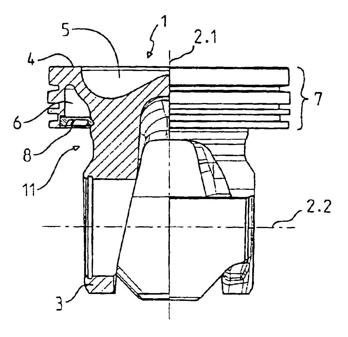
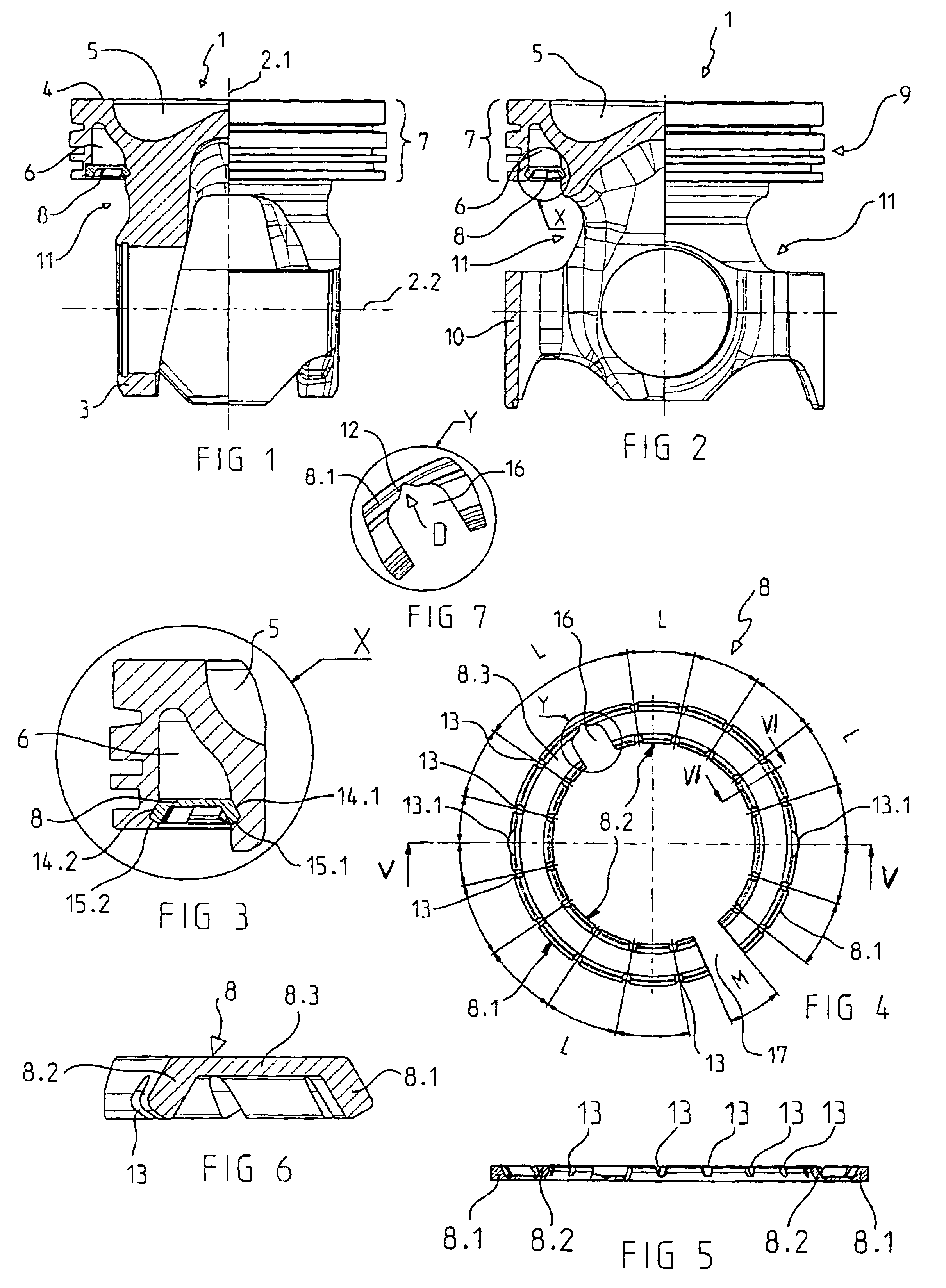
[0025]Referring now in detail to the drawings, FIG. 1 shows a one-piece piston 1 for an internal combustion engine, in a cross-sectional diagram that consists of two halves, the left half representing a cross-section of the piston 1 along a longitudinal axis 2 of the piston, and the right half representing a longitudinal axis of the piston 1 that is offset from the former by 90°.

[0026]Piston 1 is made of steel and has a piston crown 9 having a piston ring band 7 and a piston head 4 having a combustion space depression 5, whereby the piston shaft 10 is connected with the piston hubs 3 suspended on the piston crown. At the level of piston ring band 7, a closed cooling channel 6 that runs around the circumference in ring shape is arranged in piston crown 9, the radial outer delimitation and radial inner delimitation of which channel are determined by the ring wall molded onto the piston head 4 and by the piston crown region on which piston hubs 3 are suspended. The inside of the coolin...


PUM

PropertyMeasurementUnit
ridge lengthsaaaaaaaaaa
widthaaaaaaaaaa
angleaaaaaaaaaa

Abstract

A cooling channel cover for a one-piece piston of an internal combustion engine, the piston having a closed cooling channel that runs around inside the piston crown, at the level of the piston ring band, and a ring-shaped recess provided between the piston ring band and the piston shaft. The piston shaft is connected with the piston hubs suspended on the piston crown. In such a piston, an easy to assemble cooling channel cover is achieved by a one-piece plastic / spring steel ring that is U-shaped in cross-section, having a ring bottom and an outer shank around the circumference, molded onto the ring bottom and angled off radially to the outside, and an inner shank around the circumference, angled off radially to the inside. The plastic ring has a first radial division having a mouth width and a second radial division, opposite the first division, which does not separate the radially angled outer shank that runs around the circumference, to form a film hinge for radial deflection of a ring shank formed by the film hinge.

Description

BACKGROUND OF THE INVENTION[0001]1. Field of the Invention[0002]The invention relates to a cooling channel cover for a one-piece piston of an internal combustion engine, the piston having a closed cooling channel that runs around inside the piston crown, at the level of the piston ring band, and a ring-shaped recess provided between the piston ring band and the piston shaft. The piston shaft is connected with the piston crown via hubs suspended on the piston crown.[0003]2. The Prior Art[0004]A multi-part cooled piston having a cooling channel arranged in the edge region of the piston head is known from German Publication No. DE 40 39 751 A1, which channel is covered with a sheet-metal ring essentially structured like a cup spring. This sheet-metal ring is structured in one piece and can be easily assembled with the piston only because the piston is structured in two parts. In this connection, it is necessary to assemble the sheet-metal ring with the upper piston part first, before t...

Claims


Application Information

Patent Timeline
Patent Type & Authority Patents(United States)
IPC IPC(8): F02F3/16F02F3/22
CPCF02F3/22Y10T29/49249F02F2003/0007F02F3/16
Inventor GABRIEL, DIETERLAPP, MICHAEL T.
Owner MAHLE GMBH
Why Eureka
Try Eureka