Cassette for coiling optical fibers

a technology of optical fibers and cassettes, applied in the direction of optics, optical light guides, instruments, etc., can solve the problems of increasing installation stress, raising certain difficulties, and complicated mechanical devices

Inactive Publication Date: 2005-08-23
NEXANS
View PDF9 Cites 116 Cited by
  • Summary
  • Abstract
  • Description
  • Claims
  • Application Information

AI Technical Summary

Benefits of technology

[0010]The present invention seeks to provide a cassette for coiling at least one optical fiber carrying a splice with protection, the cassette enabling a long length of fiber to be stowed without increasing the surface area of the cassette, enabling problems associated with installation stresses to be overcome, and enabling different lengths of fiber to be used from their respective entry points.
[0012]By means of the invention, after the splice has been made, the two portions of ribbon are coiled in the same direction and simultaneously from their respective entry points into the cassette, and the fiber uses its own natural return force acting towards the inside peripheral wall of the cassette so as to come and press against it. As a result, the radius of curvature of the fiber is essentially determined by the wall surface and varies little during winding. This makes it possible to stow a long length of fiber without any need to increase the area of the cassette.
[0013]In addition, the fiber takes up its natural position inside the cassette and this position is not constrained by the splice protection being secured; installation stresses are thus very low.
[0015]Advantageously, said two entry points coincide. The cassette is then mechanically simpler and easier to stack if it is placed in an organizer for superposable cassettes.
[0016]In an embodiment, the cassette is for mounting in an organizer for superposable cassettes, in which case the cassette includes a flexible arm for pivoting relative to said organizer between a closed position and an open position, said arm enabling said fiber to be conveyed between the organizer and said entry point of said cassette, the length of the guide path for said fiber between said closed and open positions remaining constant. This cassette makes it possible to avoid any need to cope with an extra length on each opening / closing operation in the organizer. This type of organizer enables the number of cassettes to be adapted to match customer requirements and fiber capacities.
[0019]Advantageously, the cassette has fiber-holding means, said holding means being disposed close to said inside peripheral wall of the fiber so as to limit movement in translation of said fiber parallel to the inside peripheral wall. These means thus enable the fiber to be held inside the cassette when the cassette is subjected to vibration in its operating environment.

Problems solved by technology

Nevertheless, implementation raises certain difficulties.
In addition to the fact that the mechanical device is itself quite complicated, it is also necessary, for proper operation, to ensure that both ribbons connected together by a splice present the same length from their respective entry points into the device.
Otherwise, there will always be a length of ribbon that is not properly stowed and that will give rise to installation stresses which must be overcome by a person acting on the telecommunications network.
In addition, securing the splice protection gives rise to significant installation stresses that are often associated with a spring effect of the ribbon, which can no longer take up its natural position.
Such stresses can lead to undesirable twisting, and to radii of curvature of the ribbon that are not under control and that lead to light being lost by attenuation.

Method used


Image

  • Cassette for coiling optical fibers
  • Cassette for coiling optical fibers
  • Cassette for coiling optical fibers

Examples


Embodiment Construction

[0028]In all of the figures, elements that are common carry the same reference numerals.

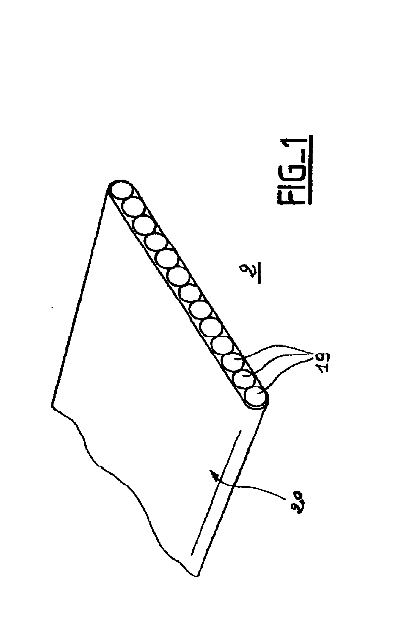
[0029]FIG. 1 is described above with reference to the state of the art.

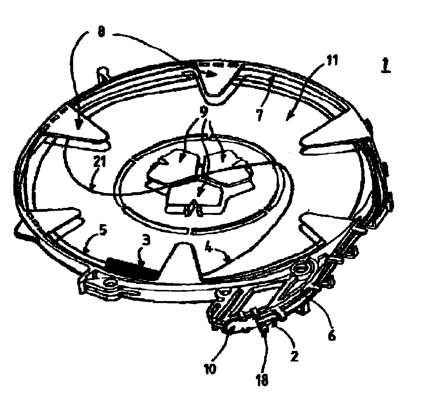
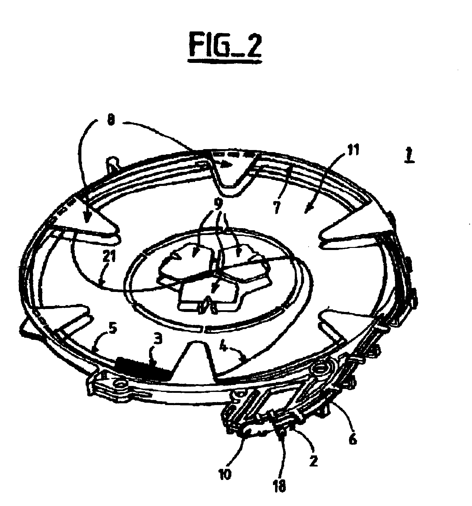
[0030]FIG. 2 shows a circular cassette 1 of the invention having coiled therein an optical fiber ribbon 2 of the kind shown in FIG. 1 and provided with a splice protection 3. The splice protection 3 subdivides the ribbon 2 into two portions 4 and 5 situated on either side of the protection 3.

[0031]The cassette 1 has a flexible entry arm 6 with a ribbon entry point 10, an inside peripheral wall 7 in the form of a circle of diameter D having holding tongues 8 secured thereto, and a bottom surface 11. The flexible entry arm 6 is provided with guide tabs 18. The cassette also has locking means 9 situated in its center.

[0032]After making the splice and its protection 3, the person acting on the telecommunications network coils the two portions 4 and 5 simultaneously going away from the entry point 10, winding the two portions 4 and...


PUM


Abstract

The present invention provides a cassette for coiling at least one optical fiber provided with a splice protection, in which said optical fiber is to be wound in such a manner as to fit closely against an inside peripheral wall of said cassette, said cassette being provided with two entry points in the vicinity of said inside peripheral wall to enable two portions of said optical fiber situated on either side of said splice protection to penetrate into said cassette. According to the invention, said entry points are provided with guide means so that said two portions wind in the same direction, and said splice protection takes up a non-predetermined position in said cassette. The present invention is more particularly adapted to coiling a flat optical fiber ribbon having a splice.

Description

[0001]The present invention relates to a cassette for coiling at least one optical fiber provided with a splice and protection for the splice, the cassette being more particularly adapted to coiling a flat ribbon of optical fibers provided with a splice.BACKGROUND OF THE INVENTION[0002]A ribbon of optical fibers comprises a set of optical fibers placed parallel to one another and embedded in a common outer coating, referred to as the “matrix”, e.g. made of a resin, the coating presenting a flat outer profile. The number of fibers grouped together in a ribbon may lie in the range 4 to 24, each fiber comprising in conventional manner a silica core of diameter less than 10 micrometers (μm), silicon cladding around the core with a diameter of about 125 μm, and a protective sheath of resin having a diameter equal to about 250 μm. FIG. 1 is thus a diagrammatic section of a ribbon 2 comprising a plurality of optical fibers 19, the ribbon 2 itself being coated in a matrix 20.[0003]In optica...

Claims


Application Information

Patent Timeline
Patent Type & Authority Patents(United States)
IPC IPC(8): G02B6/44G02B6/00
CPCG02B6/4455G02B6/4457
Inventor VINCENT, ALAINBIAUD, RICHARD
Owner NEXANS
Why Eureka
Try Eureka