Syringe With Adjustable Two Piece Plunger Rod

a plunger rod and syringe technology, which is applied in the direction of medical syringes, infusion syringes, ampoule syringes, etc., can solve the problems of inoperable syringe assembly, and achieve the effect of less packaging material, less space for storage and less packaging material

Active Publication Date: 2011-10-27
FRESENIUS KABI DEUT GMBH
View PDF10 Cites 10 Cited by
  • Summary
  • Abstract
  • Description
  • Claims
  • Application Information

AI Technical Summary

Benefits of technology

In one embodiment, the plunger rod is sized to have a length that allows the distal face of the stopper to contact the distal wall of the syringe barrel when the plunger rod is advanced distally in a fully extended locked length. In one embodiment, the distal face of the stopper does not contact the distal wall of the syringe barrel when the plunger rod is advanced distally in a locked length that is less than the fully extended locked length. In this configuration, when the thumbpress is advanced distally, the thumb press or a distal portion of the plunger rod encounters resistance against the proximal portion of the barrel that prevents further distal movement of the plunger rod in the barrel. In another embodiment, the device includes one or more intermediate locked lengths, which allow varying amounts of fluid to be expelled from the syringe.
Another aspect of the invention is that the distal and proximal portions of the plunger rod include a plurality of grooves and a projecting tab which cooperates with the grooves to provide the plunger rod with an adjustable overall length which is extendible to a plurality of different locked lengths. The grooves may be spaced axially along the proximal portion of the plunger rod and the tab may be disposed on the distal portion. Further embodiments include indicia associated with each groove to indicate the amount of fluid that will be expelled from the syringe when the plunger rod is fully advanced distally until it is stopped from further distal movement. As will be understood further below, in one embodiment, when the plunger rod is in the extended or fully extended position, the plunger rod is prevented from further distal movement when the distal face of the stopper bottoms out and contacts the distal wall of the syringe barrel. In the compressed position and in one or more intermediate positions, the stopper on the distal end of the plunger rod does not bottom out, and further distal movement of the plunger rod in the barrel is prevented when the plunger rod is stopped against the barrel, typically when the thumb press encounters the proximal end of the barrel or when some other stop prevent further distal movement of the plunger rod. In another embodiment, the indicia provide the amount of fluid that will be expelled from the syringe when the plunger rod having one or more adjusted locked lengths is fully advanced distally.
Another aspect of the invention is a tab that comprises radially inward projections which fit into the grooves to prevent relative axial movement of the distal and proximal portions of the plunger rod. According to another embodiment, the proximal portion includes an axially extending narrowed portion, which permits the tab to slide along the proximal portion and allows the distal and proximal portion to be fully extended and compressed with respect to each other. In at last one embodiment, the axially extending narrowed portion allows the tab to engage at least one of the grooves upon rotation of the proximal portion with respect to the distal portion.
One of the advantages of the present invention is that it allows the syringe barrel to be prefilled with medication and packaged with the plunger rod, in its compressed stated thereby utilizing less packaging material. This results in a lower cost device which requires less space for storage. Another aspect of the invention is that the adjustable plunger rod allows a user to adjust the amount of medication to dispense based on the patient's requirement.

Problems solved by technology

However, such syringes in which the plunger rod breaks into pieces render the syringe assembly inoperable because the plunger rod can no longer be advanced within the barrel of the syringe.

Method used


Image

  • Syringe With Adjustable Two Piece Plunger Rod
  • Syringe With Adjustable Two Piece Plunger Rod
  • Syringe With Adjustable Two Piece Plunger Rod

Examples


third embodiment

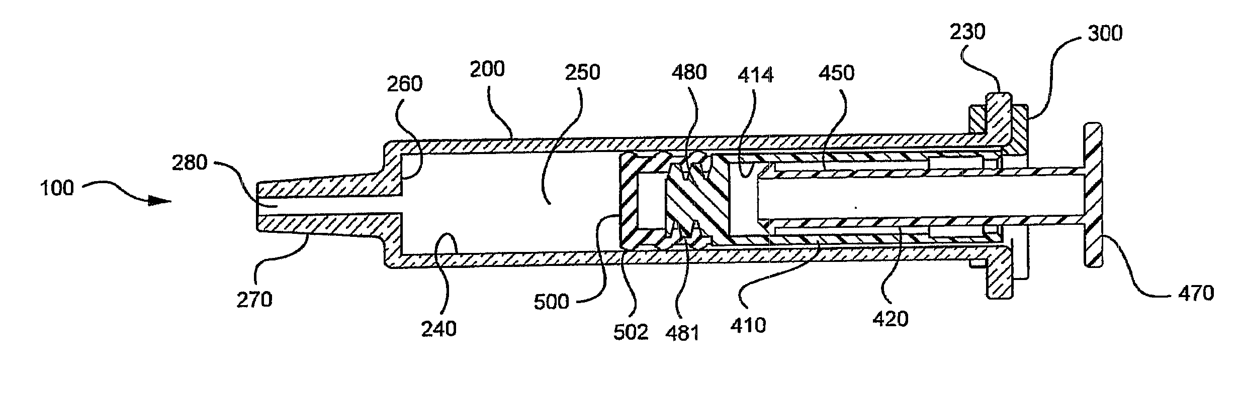
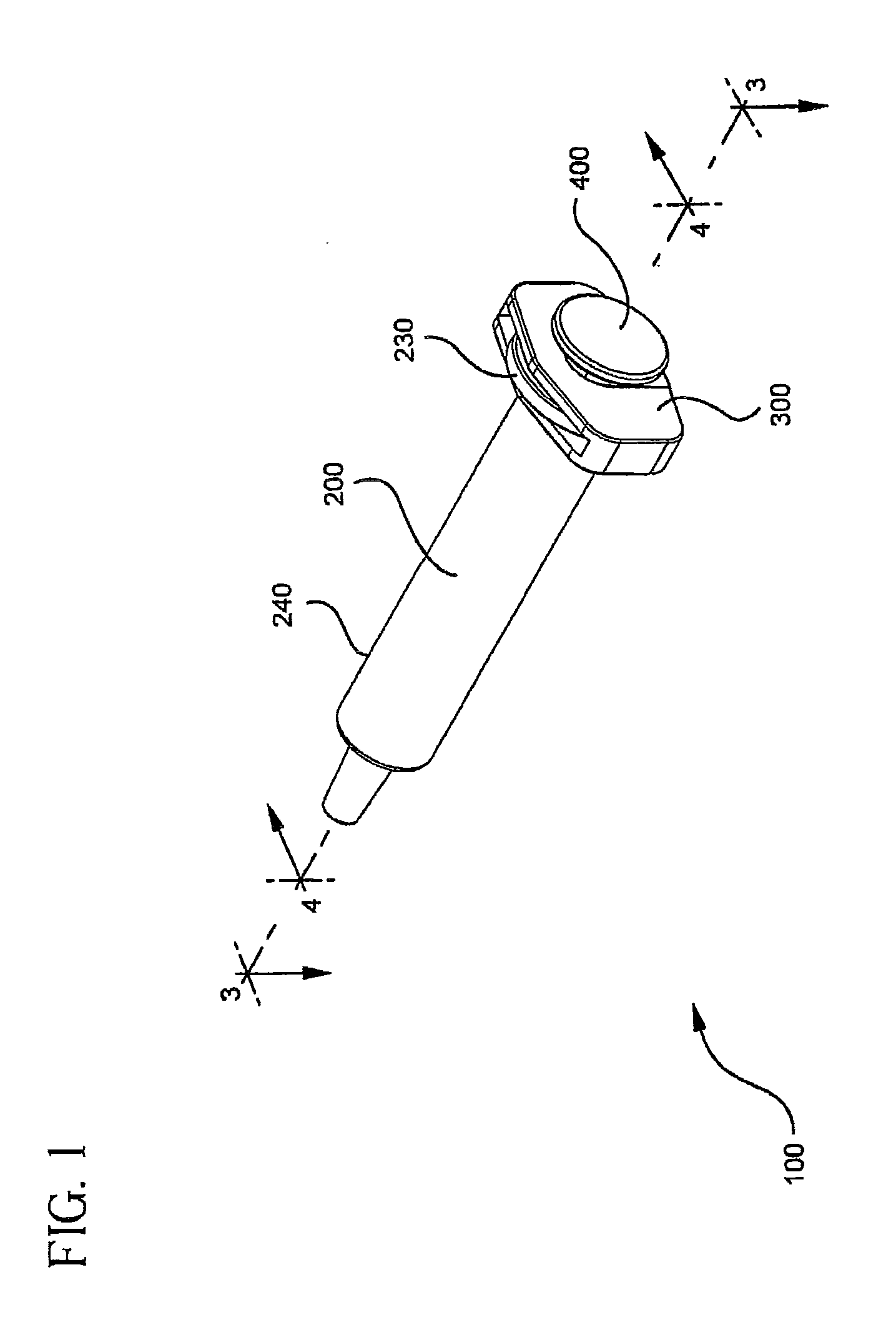
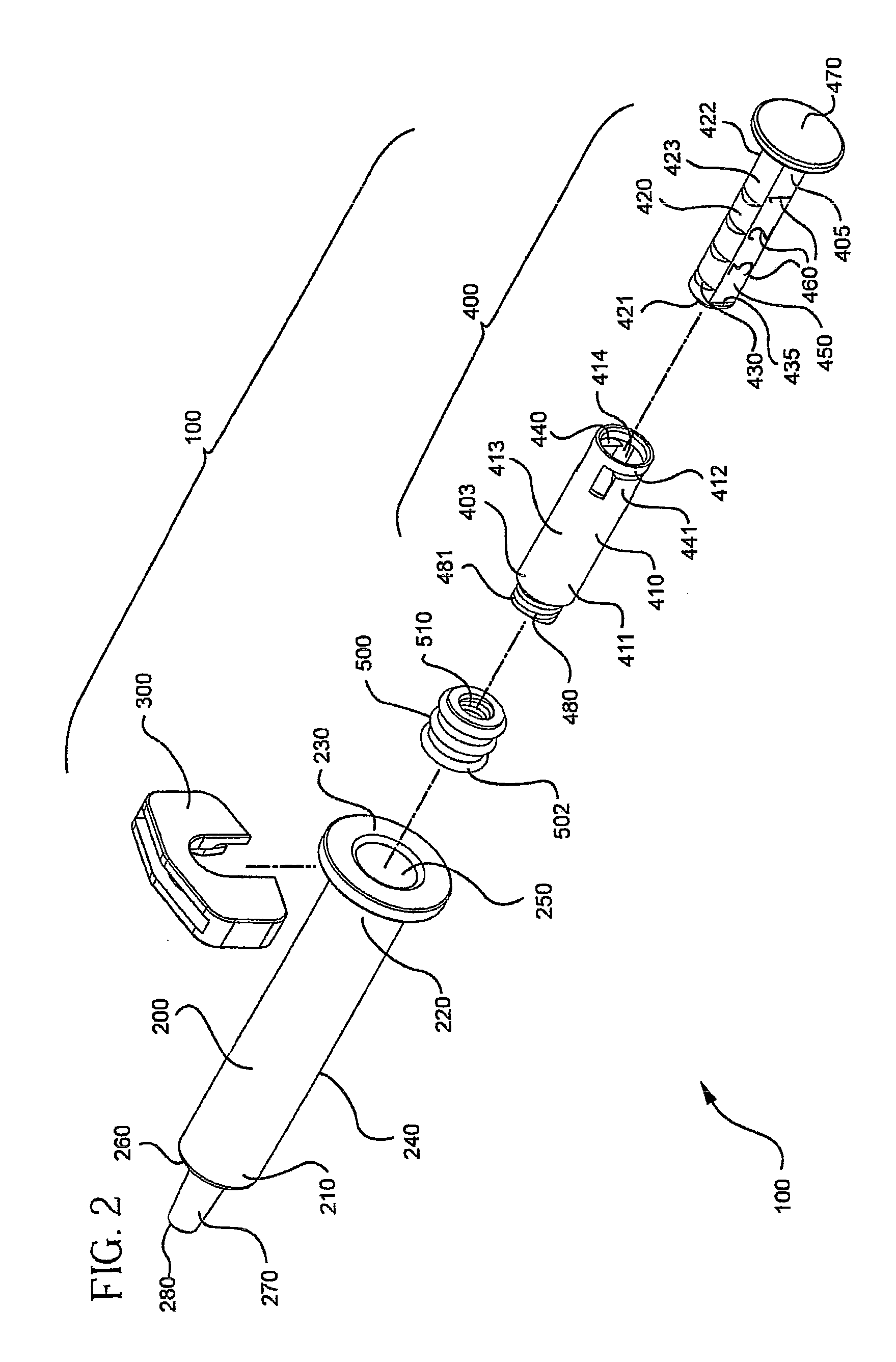
A third embodiment is shown in FIGS. 14-18, which utilizes a ratchet-like system to adjust the length of the plunger rod 700 by increments. The length of the plunger rod 710 is adjusted without the use of rotational forces. The plunger rod 700 includes a female portion 710, having a distal end 711 and a proximal end 712, and a male portion 720, having a distal end 721 and a proximal end 722. The female portion 710 and male portion 720 engage to adjust the length of the plunger rod 700. A plurality of teeth 730 are spaced axially along the length of the male portion 720 and a thumbpress (not shown) at the proximal end of the male portion 720. In the embodiment show in FIGS. 14-18, the thumbpress is covered by a thumbpress cap 800. The male portion 720 further includes a flat 750 which also includes indicia or markers 760 disposed thereon for indicating the amount of fluid expelled from the syringe when operated with a plunger rod having a specified length. The markers 760 in the embo...


PUM


Abstract

Medical devices comprising a syringe barrel and a two-piece plunger rod are provided. According to one or more embodiments, the two-piece plunger rod includes a distal portion and proximal portion slidably mounted to the distal portion. The distal and proximal portions include a tab and plurality of grooves which engage to adjust the overall length of the plunger rod to a plurality of locked lengths. The locked lengths of the plunger rod permit varying amount of fluid to be expelled from the barrel.

Description

TECHNICAL FIELDThe present invention relates to medical devices having a syringe barrel and a two-piece plunger rod which allows its length to be adjusted.BACKGROUNDSyringes generally comprise an elongate single piece plunger rod disposed in a barrel. Generally, the plunger rod is of one piece construction. Syringes that have breakable plunger rods, which break upon application of force into two or more piece, have been used to prevent reuse of syringes. However, such syringes in which the plunger rod breaks into pieces render the syringe assembly inoperable because the plunger rod can no longer be advanced within the barrel of the syringe.In applications where the syringe is prefilled with fluid and then packaged for delivery to the user, the length of the single piece plunger rod must at least long enough to accommodate the full length of the barrel. Such prefilled syringes act as the storage container for the fluid and must be packaged in such a way to accommodate the prefilled s...

Claims


Application Information

Patent Timeline
Patent Type & Authority Applications(United States)
IPC IPC(8): A61M5/315
CPCA61M5/002A61M5/28A61M5/31511A61M2005/31518A61M5/3156A61M5/3158A61M2005/3139A61M5/31555
Inventor JANISH, JAMESSEBREE, MARKKOPF, GLENN D.
Owner FRESENIUS KABI DEUT GMBH
Why Eureka
Try Eureka