Toner-supplementing device and toner-agitating member
Inactive Publication Date: 2005-08-23
MURAKAMI YUKIYOSKI
View PDF1 Cites 6 Cited by
Summary
Abstract
Description
Claims
Application Information
AI Technical Summary
This helps you quickly interpret patents by identifying the three key elements:
Problems solved by technology
Method used
Benefits of technology
Benefits of technology
[0009]It is an object of the present invention to overcome the various problems of the prior art described above and to provide a small-sized toner-supplementing device used in an image-forming device having a superior operating characteristic, superior maintenance and image quality and having no dispersion in supplying of toner and a convenient toner-agitating member used in the toner-supplementing device.
Problems solved by technology
The structure using the aforesaid prior art developer device and the toner-storing unit had a problem that a size of the developer device was increased as a storing amount of toner was increased and in particular in the case of a tandem full-color image-forming device or the like, four developer devices were installed to cause a large-sized formation of the device to be promoted.
In addition, the method for dropping toner to a predetermined width of the toner-supplementing unit had a problem that toner was leaked at the time of replacement of the toner cartridge to cause an operator to stain his or her hands or to cause the device to be stained because a size of a toner-receiving port was large and this disadvantage should be overcome in view of operation and repair or maintenance work for the device.
Hei 7-199625, they showed a problem that an image was badly influenced due to deterioration of toner caused by an excessive agitation or a problem that an amount of storage of toner at both ends of the toner-supplementing unit was increased to cause a pressure of toner to be increased and bad influence to be applied to the image because the toner was uniformly supplemented over an entire width in such a way that the toner was always adapted for the maximum width medium specified for the device without being related to a size of the medium such as a paper to be printed.
Method used
Image
Click on the blue label to locate the original text in one second.
Reading with bidirectional positioning of images and text.
Examples
first embodiment
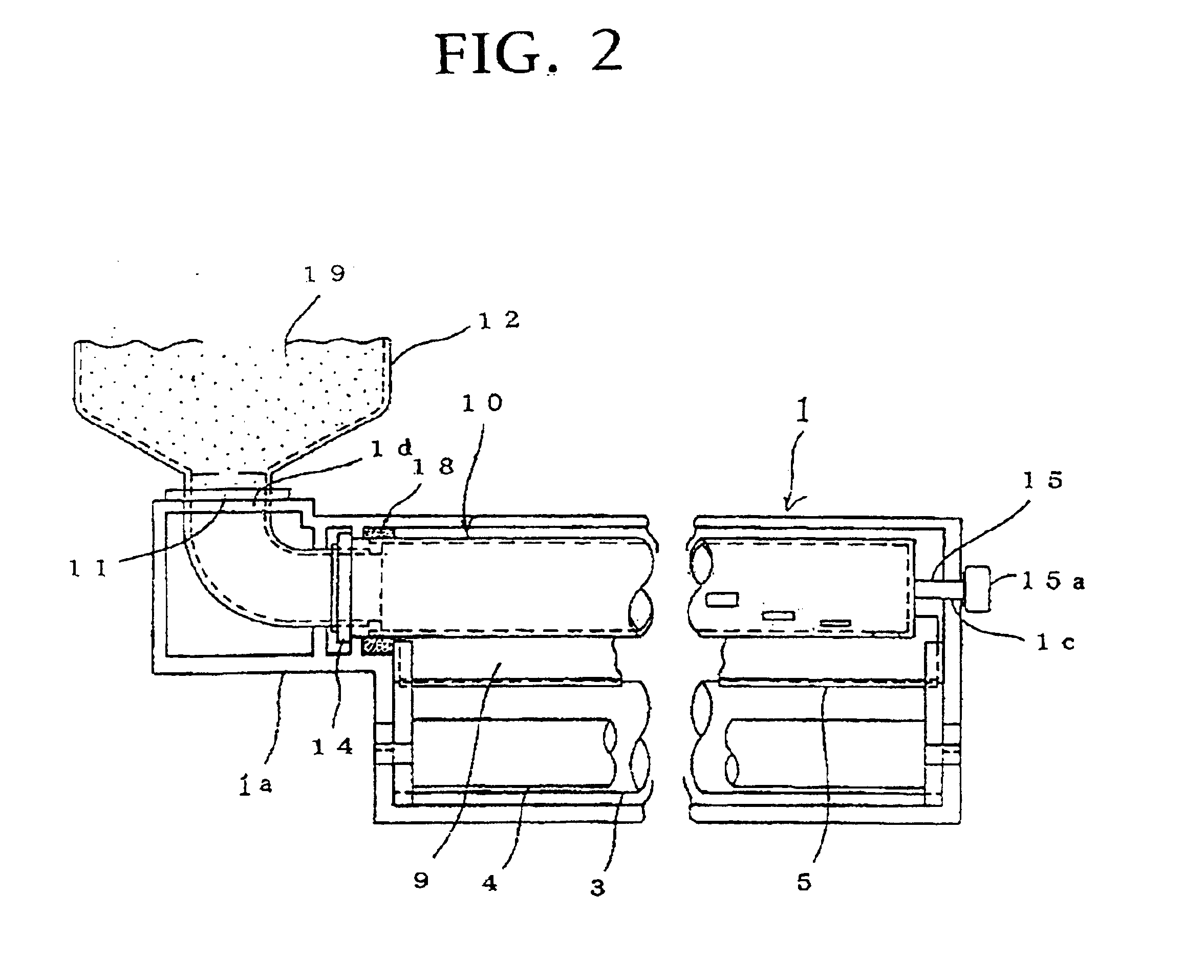
[0026]At first, referring to FIGS. 2 to 4, a toner-supplementing device 10-1 in accordance with the present invention will be described.
[0027]The toner-supplementing device 10-1 is installed between the toner cartridge 12 and the hopper 9, and has a toner-supplementing cylindrical member 13, conduit 16, coil spring 17, bushing 14 and seal member 18.
[0028]The toner-supplementing cylindrical member 13 is a cylinder having an opening end 13a at its one end (a toner-supplementing upstream side, the left side in FIG. 3, which are similarly applied to each of the following descriptions), and this is arranged substantially in a horizontal orientation so as to oppositely face against the toner-transferring roller 4. A length of the toner-supplementing cylindrical member 13 in its axial direction is set to be substantially the same axial length of the toner-transferring roller 4. Then, the opening end 13a is fixed to the ring-shaped bushing 14. The bushing 14 is rotatably engaged with a bear...
second embodiment
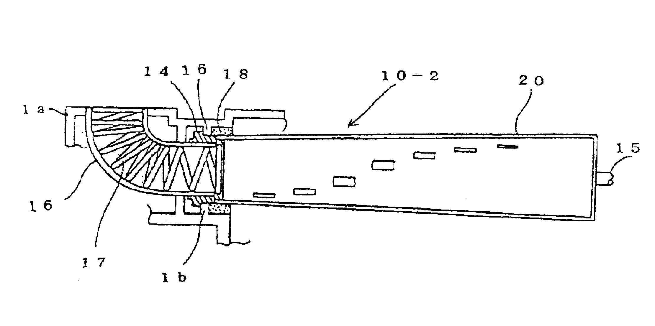
[0037]Next, referring to FIGS. 5 and 6, a toner-supplementing device 10-2 of the present invention will be described as follows.
[0038]In FIG. 5(a), a toner-supplementing cylindrical member 20 is a conical cylinder of which diameter is reduced continuously and gradually from one opened end toward a downstream direction where the toner 19 is transferred. Then, as shown in a developed view of FIG. 6, the toner-supplementing cylindrical member 20 has some toner-supplementing ports 20d arranged within a length range L of the toner-supplementing cylindrical member 20 in the same manner as that of the toner-supplementing device 10-1 of the first embodiment.
[0039]Further, as a modified embodiment of the toner-supplementing device 10-2 of the second embodiment, it may also be applicable that a toner-supplementing cylindrical member 20′ of the cylinder having the same diameter over its entire length is inclined as shown in FIG. 5(b) and a circumferential wall position is arranged to descend t...
third embodiment
[0041]Next, referring to FIGS. 7 and 8, a toner-supplementing device 10-3 of the present invention will be described as follows.
[0042]In FIG. 7, the toner-supplementing cylindrical member 21 has a substantial same inner diameter as that of the conduit 16. Then, the coil spring 17 having its outer diameter slightly smaller than an inner diameter of each of the toner-supplementing cylindrical member 21 and the conduit 16 is extended over the entire length of the conduit 16 and toner-supplementing cylindrical member 21, and the other end 17a of the coil spring 17 is fixed to the inner wall of the closed end 21b of the toner-supplementing cylindrical member 21. Further, the coil spring 17 in the toner-supplementing cylindrical member 21 may be replaced by an auger as a modified embodiment of the third embodiment.
[0043]As illustrated in the developed view of FIG. 8, the toner-supplementing cylindrical member 21 has some toner-supplementing ports 21d arranged in the same manner as that of...
PUM
Abstract
In order to develop a toner-supplementing device and a toner-agitating member used in an image forming device which are small in size, superior in their maintenance and image quality as well as their operability and have no dispersion in supplying of toner, the toner-supplementing device of the present invention is made such that a toner-storing segment is placed outside an image-forming range of the image-forming device, toner is transferred from the toner-storing segment to a toner-supplementing segment of a developer device and the toner is supplemented to a toner-supplementing area having a predetermined width at the toner-supplementing segment, wherein there are provided a conduit having an upstream side one end fixed to the developer device; a cylindrical member closely contacted with the other end of the conduit, rotatable around its axis, having its central segment being placed on an inclined line in respect to an axial direction in a developed plane of a circumferential wall segment and having a desired number of small slit-like toner-supplementing ports punched with their phase being displaced in a circumferential direction and in parallel with the axial direction; and a toner-transferring member for transferring the toner from the upstream one end toward the other downstream end inside the toner-supplementing cylindrical member.
Description
BACKGROUND OF THE INVENTION[0001]1. Field of the Invention[0002]This invention relates to an improvement of a toner-supplementing device in an image-forming device such as a printer, copyingmachine and facsimile or the like having a toner-storing unit out of an image-forming range so as to transfer and supplement toner from the toner-storing unit to a toner-supplementing unit of a developer device, and an improvement of a toner-agitating member used in the toner-supplementing device.[0003]2. Description of the Related Art[0004]In the prior art toner-supplementing unit in the image-forming device, it is generally applied to have a method for installing a toner cartridge, for example, as a toner-storing unit having substantially the same length in regard to an axial direction of the toner-supplementing roller and dropping toner directly from the toner cartridge to a predetermined width of the toner supplementing unit storing the toner-supplementing roller of the developer device beca...
Claims
Application Information
Patent Timeline
Application Date:The date an application was filed.
Publication Date:The date a patent or application was officially published.
First Publication Date:The earliest publication date of a patent with the same application number.
Issue Date:Publication date of the patent grant document.
PCT Entry Date:The Entry date of PCT National Phase.
Estimated Expiry Date:The statutory expiry date of a patent right according to the Patent Law, and it is the longest term of protection that the patent right can achieve without the termination of the patent right due to other reasons(Term extension factor has been taken into account ).
Invalid Date:Actual expiry date is based on effective date or publication date of legal transaction data of invalid patent.

