Fingerprint identification device equipped with a user recording unit

Inactive Publication Date: 2005-10-25
ORMON CORPORATION
View PDF17 Cites 5 Cited by
  • Summary
  • Abstract
  • Description
  • Claims
  • Application Information

AI Technical Summary

Benefits of technology

[0014]The fingerprint identification device to identify fingerprints disclosed above provides that the fingerprint data input via the reader unit be stored. When a malfunction occurs, a user can try to access the fingerprint data and in this way ascertain whether the cause of the problem is in the step prior to obtaining the data or subsequent to it. This will help determine the source of the malfunction. This design thus makes it easier to ascertain the location of a malfunction when doing inspections or repairs.
[0015]All fingerprint data are stored when someone touches the fingerprint reader unit. It also happens when an unauthorized person attempts to touch the reader unit in order to gain access. This provides a psychological deterrent effect. If the fingerprint identification device is installed in a car or on the door of a building, it will prevent the car from being stolen or deter any unauthorized person from entering the building without permission.
[0017]Since in fact the only time a user's fingerprint data needs to be saved is when the match is unsuccessful, choosing this expedient allows economies to be realized in the memory capacity of the user recording unit. This also make it less likely that the memory of the user recording unit will fill up so that fingerprint data can no longer be recorded.
[0019]In this embodiment, the fingerprint pattern (i.e., the optical pattern, the electrical pattern, the compressed data, etc.) is recorded in the user recording unit. This allows a greater quantity of fingerprint data to be used and enables the user to make a detailed diagnosis of the location and cause of a malfunction. And since the fingerprint itself can be restored, the fingerprint identification device can be particularly effective in preventing car theft or unauthorized entry to a building.
[0021]In this embodiment, only the data representing the feature count extracted from the fingerprint pattern is saved. As a result, only a small quantity of data needs to be saved in the user recording unit. This allows the memory capacity in the user recording unit to be put to its best use.
[0023]Since this embodiment saves the recording history along with the fingerprint data, the user can investigate the cause of a malfunction by referring to the date and time that the fingerprint identification device first showed signs of trouble. Recording the date in a recording history also is an effective deterrent to car theft and unauthorized entry by providing additional information about the car theft or unauthorized entry.

Problems solved by technology

If this sort of failure occurs frequently, the device needs to be repaired, and someone needs to ascertain where the malfunction is occurring.
Failures of this sort may be due to a number of causes.
The prism of the read-in unit may be scratched; the person's finger may be dirty; or there may be foreign matter stuck to the read-in unit or the finger.
If any of these things happen, they may cause a problem in the data compression routine used by the image data processing unit to compress the fingerprint pattern, or the features which distinguish one individual's pattern from another's may be difficult to extract, or a problem may occur in the comparison program.
Therefore, such prior art devices to identify fingerprints require much time and effort to determine the cause and the location of a malfunction before any repairs could be made.

Method used


Image

  • Fingerprint identification device equipped with a user recording unit
  • Fingerprint identification device equipped with a user recording unit
  • Fingerprint identification device equipped with a user recording unit

Examples


Embodiment Construction

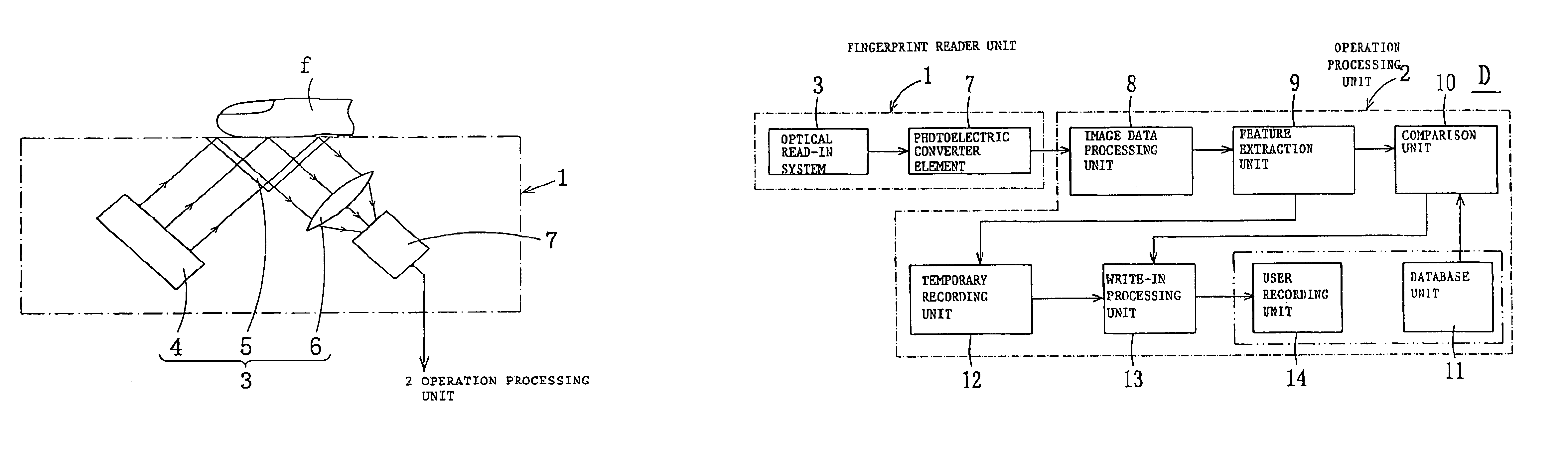
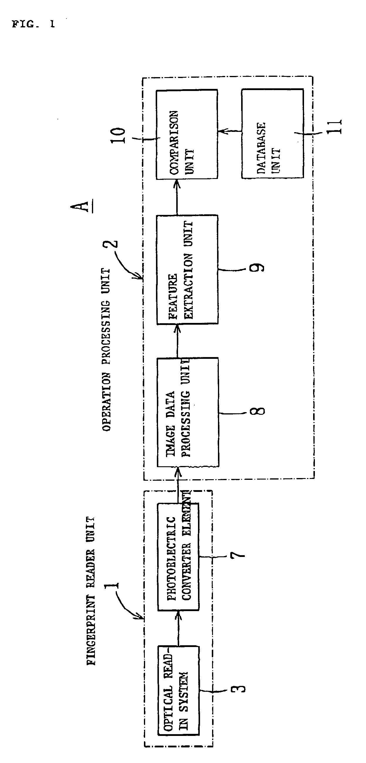
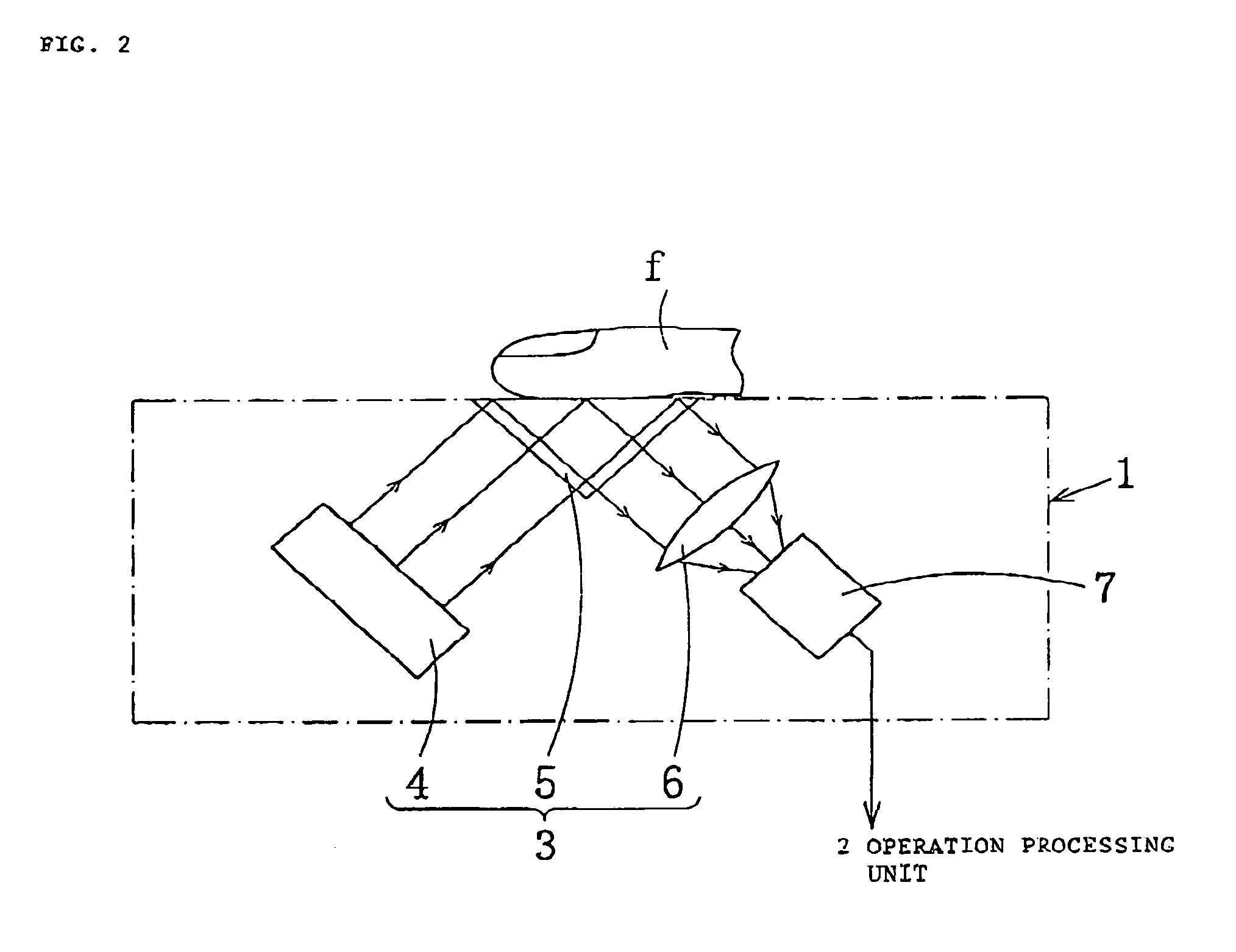
[0032]FIG. 3 is a block diagram of a fingerprint identification device B to identify fingerprints, according to the first preferred embodiment of this invention. Fingerprint identification device B consists of a fingerprint reader unit 1 and an operation processing unit 2. Fingerprint reader unit 1 consists of an optical reading system 3 and a photoelectric converter element 7. An actual appearance of the fingerprint identification device is as shown in FIG. 2. When the person places his finger on optical reading system 3, his fingerprint pattern is read optically. This optical fingerprint pattern is converted by photoelectric converter element 7, such as a CCD or the like, to binary electrical signals (i.e., to image data) and output.

[0033]Operation processing unit 2 includes an image data processing unit 8, a feature extraction unit 9, a comparison unit 10, a database unit 11, a temporary recording unit 12, a write-in processing unit 13 and a user recording unit 14. Database unit ...


PUM


Abstract

A fingerprint identification device to identify fingerprints is equipped with a fingerprint reader unit to input a fingerprint to be detected and a database unit to record a fingerprint database which is provided in advance. A fingerprint comparing unit identifies the input fingerprint via the fingerprint reader unit by comparing with the fingerprint database recorded in the database unit and a user recording unit records the input fingerprint input by the fingerprint reader unit.

Description

FIELD OF THE INVENTION[0001]This invention relates to a fingerprint identification device which can discriminate between different individuals by their fingerprints. Specifically, the fingerprint identification device according to present invention is equipped with a user recording unit. The user recording unit records the fingerprint of users for the purpose of the maintenance, repair or for providing higher security.BACKGROUND OF THE INVENTION[0002]FIG. 1 is a block diagram of a prior art finger identification device A to verify fingerprints. Fingerprint identification device A includes a fingerprint reader unit 1 including an optical read-in system 3 and a photoelectric converter element 7, and an operation processing unit 2.[0003]FIG. 2 shows a configuration of the fingerprint reader unit 1. Optical read-in system 3 consists of a light source 4, such as a light-emitting diode or the like; a triangular prism 5, to which a person's finger f is applied, and which selectively emits ...

Claims


Application Information

Patent Timeline
IPC IPC(8): A61B5/117G06K9/00G06T1/60G06T7/00G06T1/00
CPCA61B5/1172G06K9/00006G06K9/00087A61B5/7232G06V40/12G06V40/1365G06F18/00
Inventor ISHII, HIROTAKAMORITA, TAKEOYOMO, YASUHIDE
Owner ORMON CORPORATION
Why Eureka
Try Eureka